RS-1_instruction manual.pdf - 第736页
Part 2 D etaile d Descript ion of E ach Functi on Chapter 8 Machine Set up 8- 28 ( 2) How to set 1) Default back hei ght a) W he n the unit i s mm, a value of - 0. 5 to 4 8 can be set . 2) Support table overstroke (av ai…
Part 2 Detailed Description of Each Function Chapter 8 Machine Setup
8-27
Support table
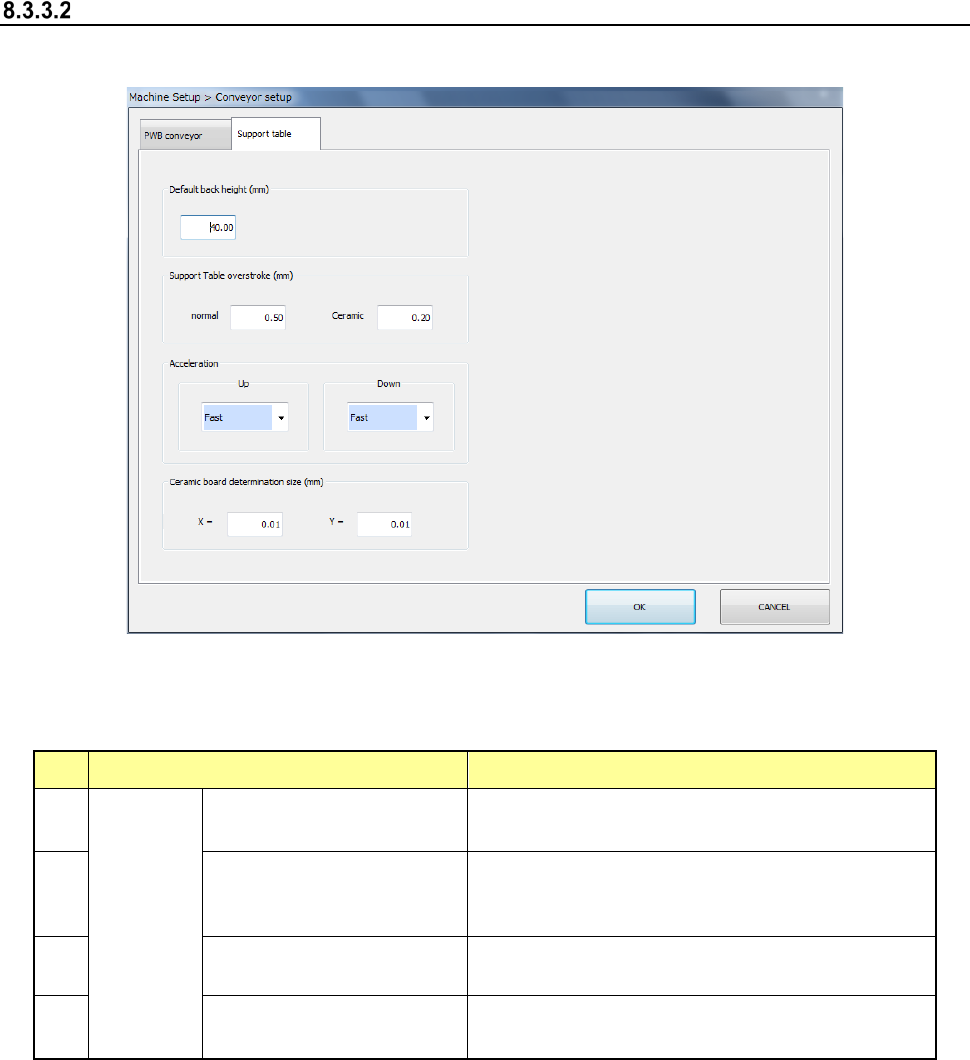
When you select [Support table], the following screen appears.
When you click each tab, you can specify [PWB conveyor] or [Support table].
(1) Setting item
No. Item Description
1
Support
table
Default back height (*2)
Set the PWB lower limit value of the support
table.
2
Support Table overstroke
(*2) (usually ceramic (*1))
Set the inserting stroke of the support table.
3
Acceleration (*2)
(ascent, descent)
Set the acceleration of the support table.
4
Ceramic board
determination size (X, Y)
Set the ceramic board size.
*1 Stroke in the item of ceramic
When "The ceramic board is used" of production, etc. is checked and the board size (XY)
is less than 150 mm, it is judged that the ceramic board is used and the stroke input to the
item of ceramic is used. As for the PWB other than the ceramic PWB, the stroke input to
the item of ceramic is applied when a PWB size of less than 150 mm and an optional
operation are set. However, a usual stroke is applied for the PWB of 150 mm or more as
for the ceramic PWB.
*2 If a production program makes settings of the conveyor, those settings are applied here.
Part 2 Detailed Description of Each Function Chapter 8 Machine Setup
8-28
(2) How to set
1) Default back height
a) When the unit is mm, a value of -0.5 to 48 can be set.
2) Support table overstroke (available only when a board is transported with the
single-lane conveyor)
a) When the unit is mm, a value of 0.00 to 5.00 can be set.
3) Acceleration
a) This item can be set by 4 steps from the combo box.
4) Ceramic board determination size
a) When the unit is mm, a value of 50.00 to 905.00 can be set.
Part 2 Detailed Description of Each Function Chapter 8 Machine Setup
8-29
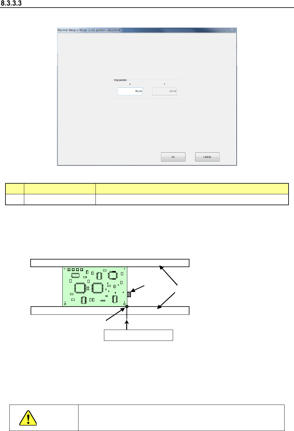
Shape clamp position adjustment
When you select “Shape clamp position adjustment,” the following screen appears.
- “Shape clamp position adjustment” screen
(1) Setting item
No. Item Description
1 X Board clamp stop position with the conveyor stopper
(2) How to set
Perform teaching to enter data on this screen.
Example: When a board is transferred from left to right
To perform teaching, set the conveyor stopper to ON in advance.
Conveyor
Conveyor
stopper
Shape reference position
X (stop position)
* Adjust the rail support (stopper main unit) so that the X-direction position of the tip of the
stopper pin is set as shown below according to the board specifications:
- Standard/XL board specifications
When a board is transferred from left to right: 781.6± 0.5 mm
When a board is transferred from right to left: 131.6 ± 0.5 mm
CAUTION
To avoid a risk of injury, do not put your hand in the machine, nor move
your face or head close to the machine while the machine is teaching
data.