RS-1_instruction manual.pdf - 第822页
Pa r t 2 Det ai l ed Des c r i pti on o f Ea c h Fu nc ti on Chapter 10 M ach i ne Manage m e nt Infor m ation 10 -9 10.3.4 Oper ation I nfor mati on of e ach nozzl e The op er ation i nf orm ation of each noz zle i s c …
Part 2 Detailed Description of Each Function Chapter 10 Machine Management Information
10-8
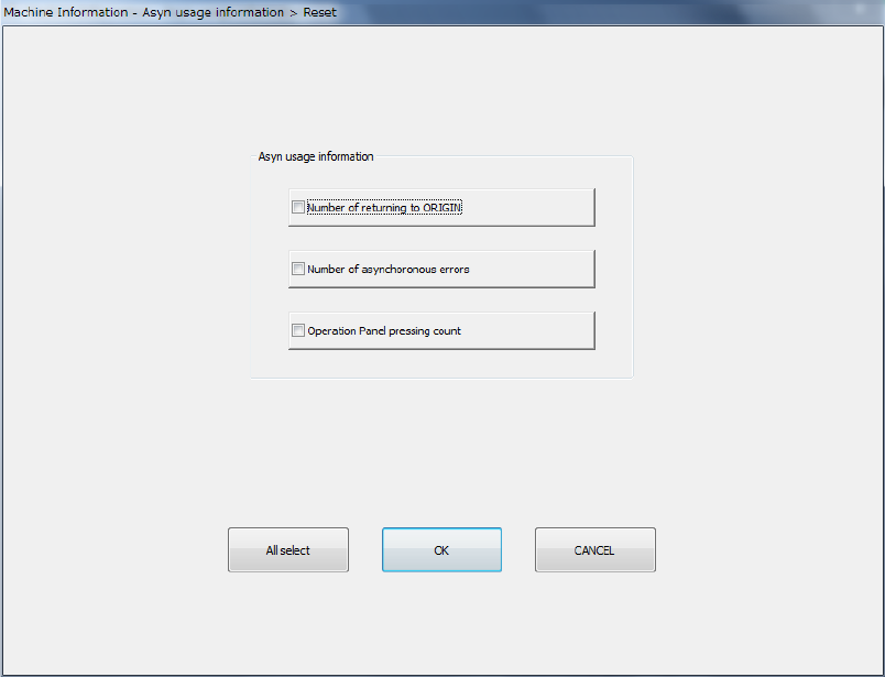
(2) <Reset> button
When you press the <Reset> button or press [Initialize] – [Reset] in the main menu, the
following screen appears.
This operation allows you to clear the certain data or all data displayed in the list.
- The <All select> button allows you to select all check boxes displayed on the screen.
- When you press the check box of the item whose data you want to reset, and press the
<OK> button, the “Question” dialog box for asking you whether to reset data appears on
the screen. When you press the <OK> button on this “Question” message, the system
resets the checked items of data, and closes the screen.
- When you press the <CANCEL> button, the system does not reset any data and the
current data is still displayed.
Part 2 Detailed Description of Each Function Chapter 10 Machine Management Information
10-9
10.3.4 Operation Information of each nozzle
The operation information of each nozzle is controlled according to the ATC number.
When you change the nozzle assignment on the ATC, you have to rewrite the corresponding
nozzle data with the command provided on this screen.
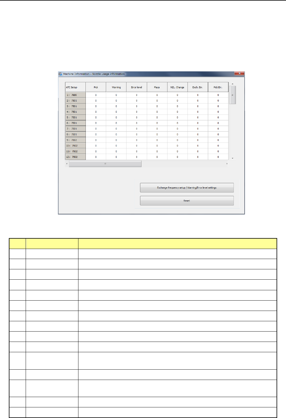
(1) Displayed screen
When you select [Machine] – [Nozzle usage information] in the main menu, the nozzle usage
information screen appears. This screen is changed over to the information on each bank
by pressing the <Select device> button.
1) List
The number of operations and the related data on each nozzle are displayed as a list here.
No.
Item
Description
1 Pick Counts how many times the nozzle picked a component totally.
2 Place Counts how many times the nozzle placed a component successfully.
3 NZL Change Counts how many times the nozzle was replaced successfully.
4 Warning Displays the warning level.
5 Error level Displays the error level.
6 Exch. Err. Counts how many times a replacement error occurred per a nozzle.
7 Pick Err. Counts how many times a pick-up error occurred per a nozzle.
8 Retry Counts how many times a component pick-up retry over error occurred.
9 LA Recog Counts how many times a laser recognition error occurred.
10 Chip Counts how many times a chip rise error occurred.
11 Dimension
Counts how many times an irregular-shaped component error occurred at
the nozzle.
12 Posture Counts how many times a component posture check error occurred
13 Presence
Counts how many times a component presence check error occurred
before placement of a component.
14 Vision recognition Counts how many times a vision recognition error occurred.
15 Sliding Fail Counts how many times sliding failed.
Part 2 Detailed Description of Each Function Chapter 10 Machine Management Information
10-10
2) <Exchange frequency setup/Warning/Error level settings> button
These buttons are described in the sub-sections later.
3) <Reset> button
This button is described in the sub-section later.
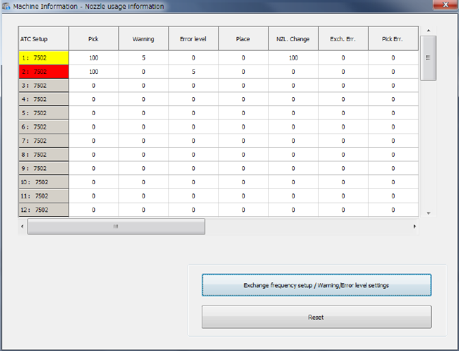
(2) Screen displayed when a warning is issued or an error occurs
When a value in the “Pick” cell exceeds that in the “Warning” cell, the nozzle is displayed in
yellow. When a value in the “Pick” cell exceeds that in the “Error level” cell, the nozzle is
displayed in red.
The signal light lighting condition does not change.