RS-1_instruction manual.pdf - 第139页
Part 1 B asic O peration Chapter 2 Pr oduction 2- 28 Other adjustments A board havi ng a notch m ay cause the PWB sensor to activate incorrect ly . Therefor e, enter the PW B transport sen sor delay tim e depend ing on t…
Part 1 Basic Operation Chapter 2 Production
2-27
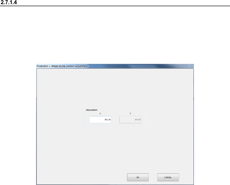
Adjusting the shape clamp reference position
When the stopper position has been adjusted, it is necessary to reset the shape clamp reference
position as shown below.
<How to change the position>
(1) Select the “Product” button from the main menu, the [Support] command, and then the [Plan
support] command.
When you press the <Shape clamp position adjustment> button, the “Shape clamp position
adjustment” screen appears.
- See Section 8.3.3.3 “Shape clamp position adjustment” for detailed setup procedures.
Part 1 Basic Operation Chapter 2 Production
2-28
Other adjustments
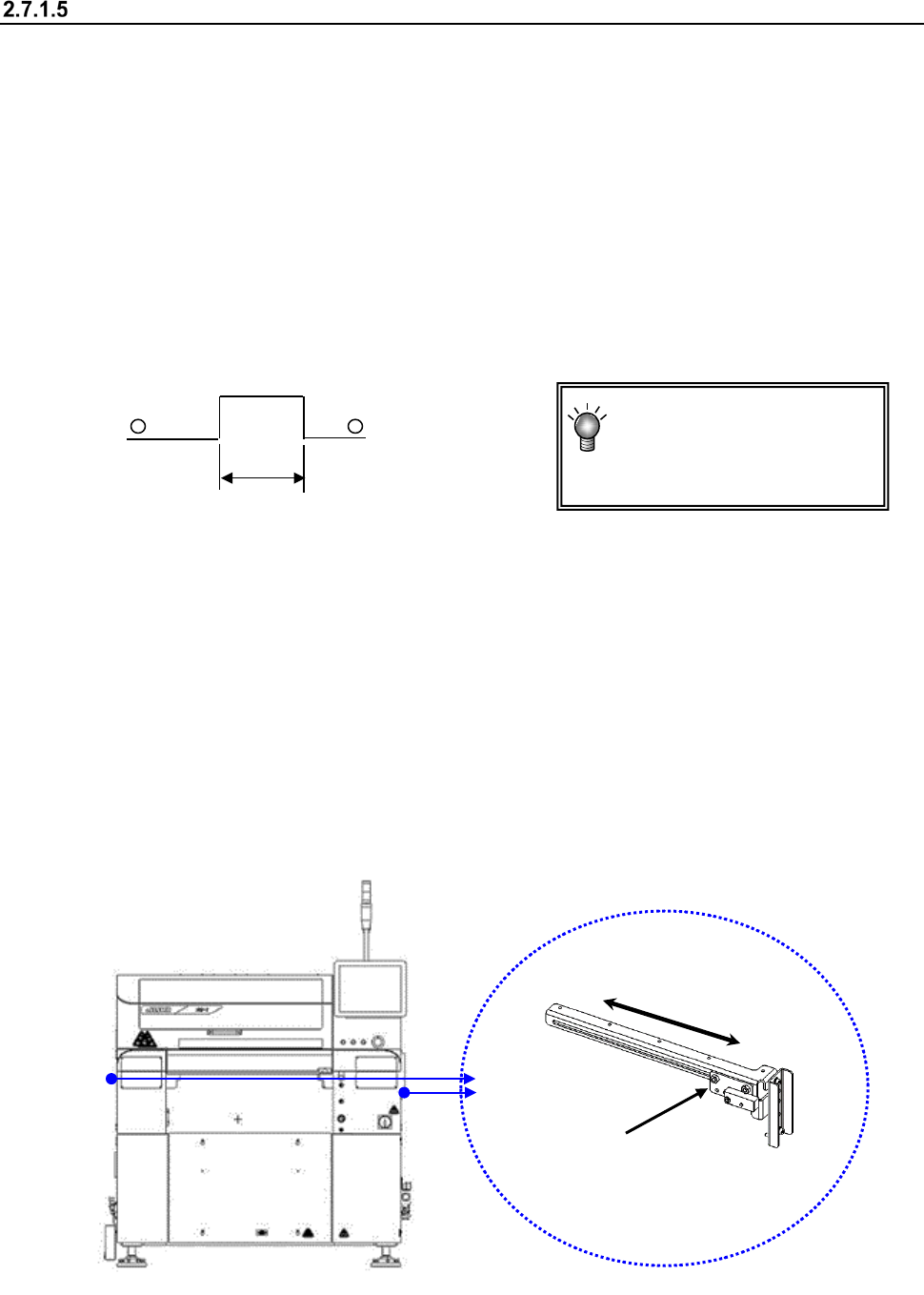
A board having a notch may cause the PWB sensor to activate incorrectly.
Therefore, enter the PWB transport sensor delay time depending on the size of a notch.
You can change the position of the stopper on the reference rail side ⑩ and that of the PWB
sensor (Y direction) also for an irregularly shaped board.
(1) PWB transport sensor delay time
<Procedure>
① Select “Program Editor - PWB data” or select the [Conveyor] command from the
“Machine Setup” menu, and the [Conveyor setup] command.
② Enter the delay time that is appropriate for the length of the notch of a board, or the
length of the notch with a keyboard.
(See Section 8.3.3.1 “PWB Transport.”)
(2) Stopper
If the PWB has a notch, etc. at its front end and the centering of the PWB is unstable, move the
stopper to another position.
See Section 2.7.1.3 “Adjusting the shape clamp reference” for the moving operation.
When the stopper assembly has been moved, reset the “Shape clamp position” in the Machine
setup.
(3) Board sensor
<Procedure for changing the board sensor position>
Hold the sensor bracket 1 to move it along the elongate hole in the direction “A.”
Check to see if a board is set with the “Conveyor” menu of the “Manual Control” utility or the
“Transport” menu of “Program Editor.”
A: Length of a notch
A
You do not have to enter the
delay time if the notch
cannot be located at any
PWB sensor.
①
A
Part 1 Basic Operation Chapter 2 Production
2-29
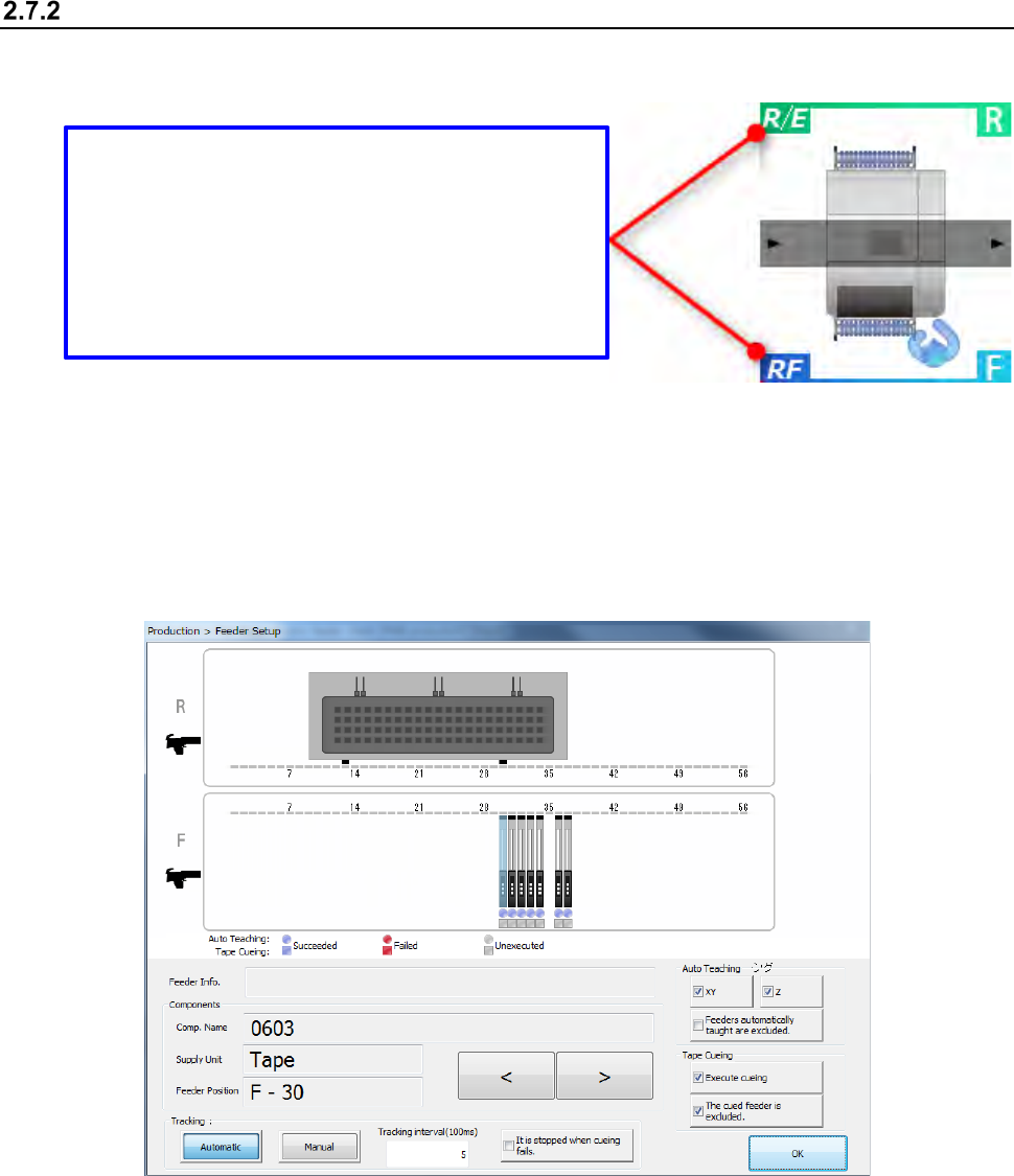
Preparation of a component supply device
Set an available feeder onto the fixed bank.
After setting the feeder, perform the component pick-up position tracking operation.
<Procedure>
① Select the [Plan support] command form the “Product” menu.
Press the <Feeder Setup> button.
The following “Feeder Setup” screen appears.
Bank type display
The current bank type is displayed.
There are feeders that cannot be used according to
the bank type.
R/E: The RF type and EF type electric feeders can
be used.
RF: The RF type electric feeder can be used.