RS-1_instruction manual.pdf - 第874页
Pa r t 2 Det ai l ed Des c r i pti on o f Ea c h Fu nc ti on Chapte r 1 1 S el f - diagnosis Func ti on 11 - 16 If a las er r ecog ni tion er r or oc cur s or the m easur em ent r esult is not w it hin the r eg ulate d r…
Part 2 Detailed Description of Each Function Chapter 11 Self-diagnosis Function
11-15
11.3.3.5.1 How to set
When you follow the instruction displayed in the “Operation” column, the machine automatically
obtains the values.
(1) Nozzle allocation
One of the nozzles whose number is from 7500 to 7503 or from 7505 to 7507 is used to
measure the height of the laser/sensor.
If any nozzle described above is not assigned to the ATC of a head to be measured, an error
occurs. If so, assign a nozzle with the menu item “ATC nozzle setup” invoked from the
“Machine Setup” screen.
(2) Selection of a head
Select a head to be measured. You can select two or more heads.
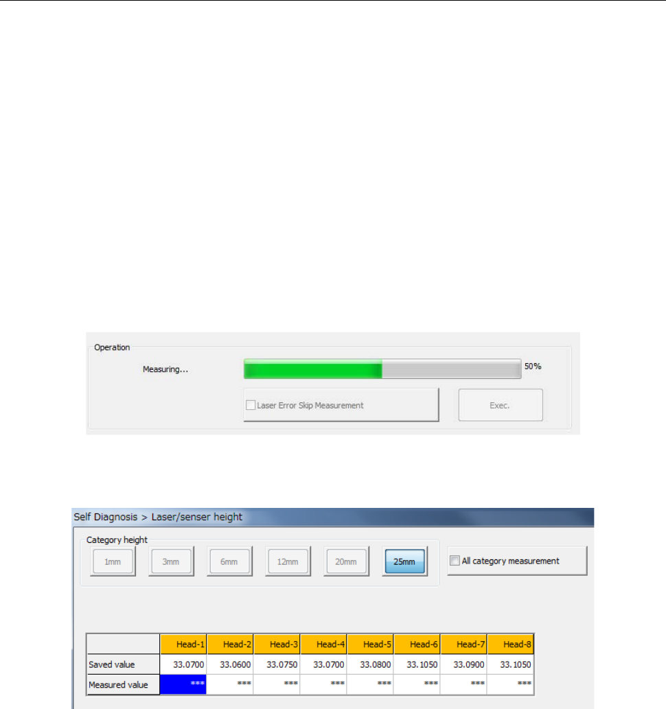
(3) Start of measurement
Press the <Exec.> button to start measurement.
The column corresponding to the head being measured is displayed in blue.
Part 2 Detailed Description of Each Function Chapter 11 Self-diagnosis Function
11-16
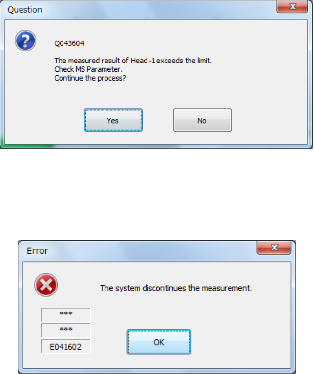
If a laser recognition error occurs or the measurement result is not within the regulated range,
the following message appears on the screen.
If an error other than above occurs: neither a laser recognition error nor measurement value
exceeding the regulated range, the machine displays the corresponding error message, and
then the following message on the screen. When you press the <OK> button on this screen,
the machine aborts measurement operation even though there is any head not measured yet.
(4) End of measurement
When the system finishes measurement, the progress bar indicates “100 %,” and the
measured values are displayed in blue.
When you press the <OK> button, the measured values become valid, but are not saved/set
yet at this point.
These values are actually set only when you quit the application. See Section 11.3.3.6.2
“Saving the setting values and exiting the screen” for details.
When you press the <CANCEL> button, the measured values become invalid.
Part 2 Detailed Description of Each Function Chapter 11 Self-diagnosis Function
11-17
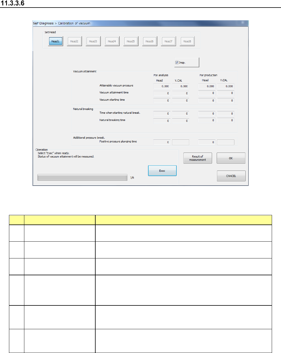
Vacuum calibration
When you select [Vacuum] in the self-diagnosis menu, the vacuum calibration dialog appears.
(1) Setting items
No. Item Description
1
Attainable vacuum
pressure
Maximum attainable vacuum pressure caught by each pressure
sensor on the head side and vacuum calibration side
2 Vacuum attainable time
Vacuum attainable time caught by each pressure sensor on the
head side and vacuum calibration side
3 Vacuum starting time
Vacuum starting time caught by each pressure sensor on the head
side and vacuum calibration side
4
Time when starting
natural break
Time required for the vacuum value to reach the pick vacuum
threshold value from the vacuum solenoid valve OFF status in
each pressure sensor on the head side and vacuum calibration
time
5 Natural breaking time
Time required for the vacuum value to reach the natural breaking
time from the vacuum solenoid valve OFF status in each pressure
sensor on the head side and vacuum calibration side
6
Positive pressure
plugging time
Time required for the vacuum value to transfer to the positive
pressure exceeding the open air pressure from the blow solenoid
valve ON status in the head-side pressure sensor.