RS-1_instruction manual.pdf - 第273页
Part 1 B asic O peration Chapter 2 Pr oduction 2- 162 Component protection If a recognitio n error occur s at a component for whic h “Protect” is specified on the “Compone nt data (Packag ing style)” scr een of a product…
Part 1 Basic Operation Chapter 2 Production
2-161
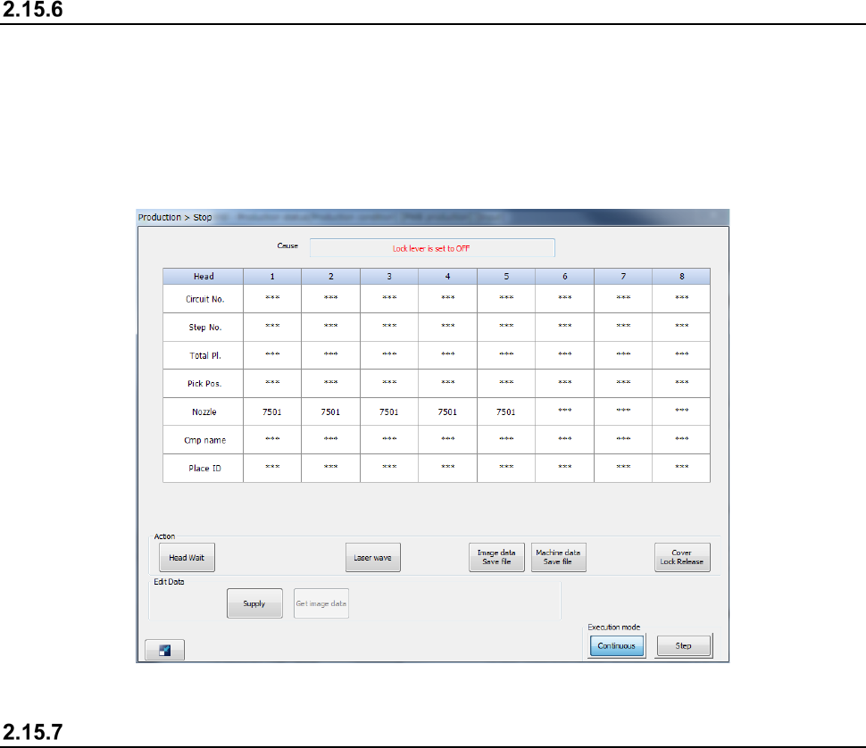
If the feeder is inserted or removed
When the feeder is removed during production, the production is paused and the Stop screen
appears as the feeder may interfere with the head during insertion or removal of the feeder.
Note that even though you remove the RF feeder in Feeder insertion/removal mode, the production
is not paused.
See the corresponding description of Section 2.15.12 “Feeder insertion/removal mode” for details of
Feeder insertion/removal mode.
If a feeder floating error is detected
If the system detects a feeder floating error, it immediately aborts the current PWB production due to
this error. If it detects a feeder floating error while the axis is operating, the servo mechanism is
turned off. To restart the suspended PWB production, the servo mechanism has to be locked.
If the system detects a feeder floating error, you cannot restart the suspended production even
though you press the <START> switch.
To restart the suspended production, set the feeder exchange trolley correctly again, and then press
the <START> switch.
See Section 2.15.1 “If an error occurs” for details.
Part 1 Basic Operation Chapter 2 Production
2-162
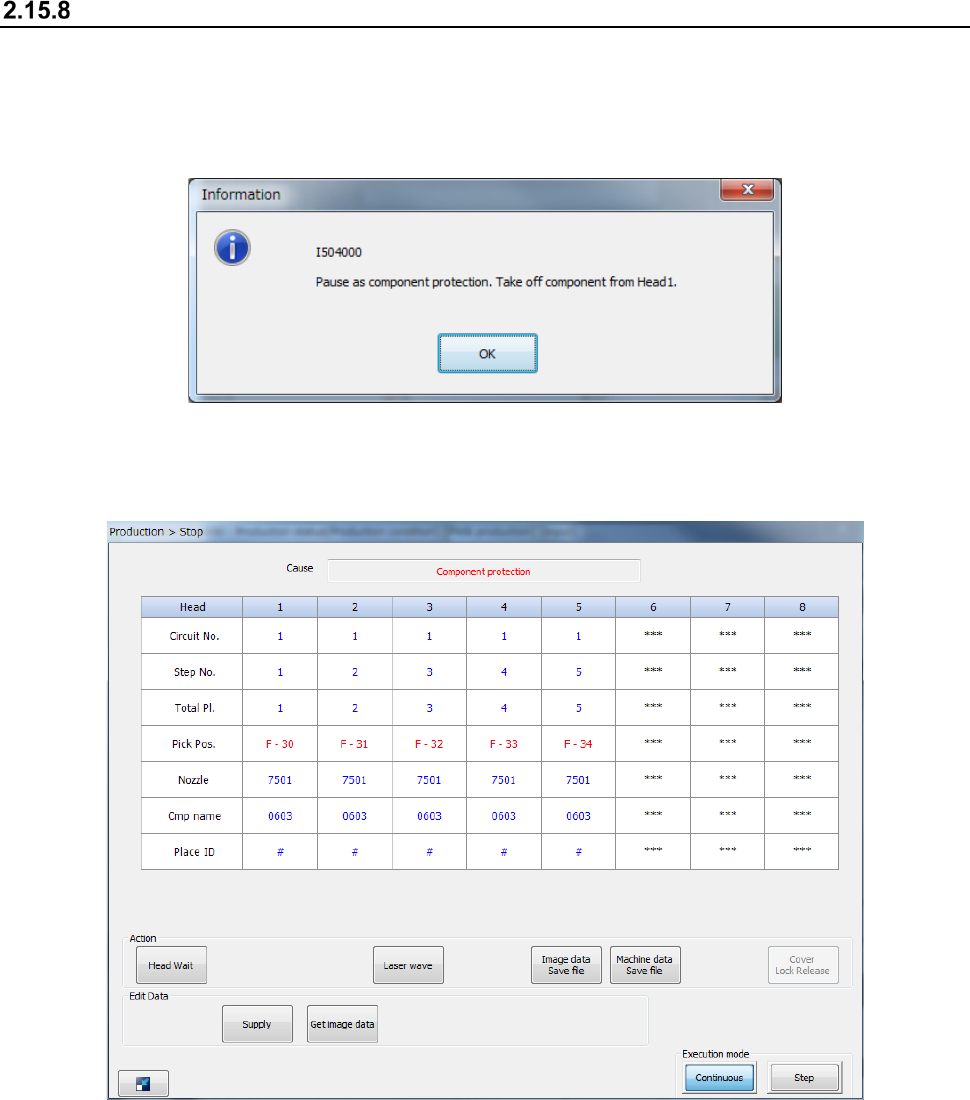
Component protection
If a recognition error occurs at a component for which “Protect” is specified on the “Component data
(Packaging style)” screen of a production program, the head unit moves to the component
protection position, and then the system displays the “Information” screen on the screen and stops
production temporarily.
When you remove a component picked up with the nozzle with hands, and then press the <OK>
button, the system displays the “Stop” screen.
When you press the <START> switch, the system restarts the suspended production after
discarding the component.
When you press the <STOP> button, the system starts terminating the suspended production.
Part 1 Basic Operation Chapter 2 Production
2-163
If the system temporarily stops due to a laser head stain error, a chip tombstone error, a laser
recognition error or an irregularly-shaped component error, the <Laser wave> button is displayed on
the screen.
If a similar error occurs at a head nozzle when the system temporarily stops due to any error, this
button is displayed also. When you press this button in such a case, the laser head moves up and
down to check whether the head is not stained or not. Pay attention to this head movement.
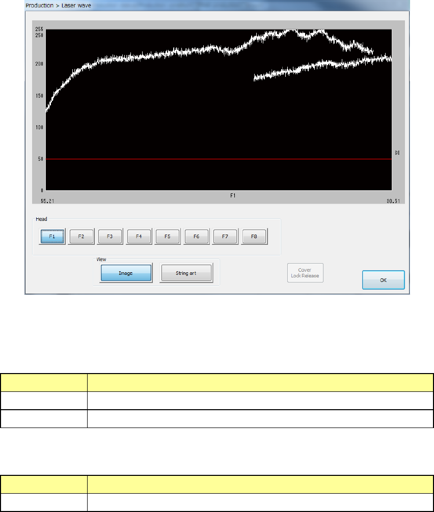
When you press the <Laser wave> button, the “Laser wave” screen appears.
(1) Laser waveform image
Image of the laser waveform is displayed here.
(2) List of “View” buttons
Select what to display on the laser waveform image.
Item Description
Image Displays the result of the image waveform.
String art Displays the result of component recognition with laser in string art.
(3) List of heads
Select a head to be displayed on the laser waveform image.
Item Description
Heads 1 through 8 Select a head to be displayed on the laser waveform image.
When you press the <OK> button, the system quits the “Laser wave” screen, and returns to the
previous screen.
See Section 2.15.1 “If an error occurs” for details.