RS-1_instruction manual.pdf - 第687页
Part 2 D etaile d Descript ion of E ach Functi on Chapter 7 Operation Option 7- 12 7.4.2 Function When you pres s the <Function> but ton, the scr een for setting the f unction o ptions for PWB production a ppears. …

Part 2 Detailed Description of Each Function Chapter 7 Operation Option
7-11
No.
Menu item
Description
Status
Operation and detailed explanation
11
Method of displaying
the worst feeder during
production
Specify the display method of the worst feeder on the production execution
screen.
Pick ratio (number of pick
successes)/total number of picks
Tot al number of errors
Three worst feeders are
displayed from the pick ratio
obtained by the number of pick
successes/total number of picks.
Three worst feeders are displayed from
the total number of pick errors.
12 Information of coplanarity
Specify how to output coplanarity information.
You can specify this menu item only when the menu item “When Copla
check fails” is set to “Pause.”
No output
The machine does not output any
coplanarity information.
Only error electrode information
The machine outputs only information
on an electrode(s) at which an error
occurred.
All electrode information
The machine outputs information on all
electrodes.
Part 2 Detailed Description of Each Function Chapter 7 Operation Option
7-12
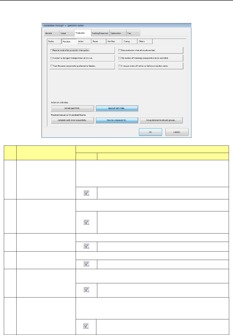
7.4.2 Function
When you press the <Function> button, the screen for setting the function options for PWB
production appears.
No. Menu item
Description
Status
Operation and detailed explanation
1
Resume mode after
production interruption.
Specify whether to display the message that asks a user to resume the
production when he/she interrupts the production (by pressing the <Pause>
key).
When production is aborted abnormally (due to an asynchronous event or
production error), the system always creates a continuous production file.
The system creates a continuous production file when the current
production is interrupted.
2
Stop production when all
circuits are bad.
Specify whether to interrupt the current production if the system recognizes all
circuits as bad marks.
The machine aborts production although it has not produced the
preset number of PWBs possibly because an error occurs: the
wrong bad mark information, sensor adjustment failure or
malfunction and so on.
3
Ignore transport at dry run.
Specify whether to perform a transport operation at dry run production.
No transport operation is performed at dry run production.
4
Manage the residual
number of components.
Specify whether to manage the residual number of components.
The residual number of components is performed.
5
Consider the same
component as an alternate
feeder.
Specify the same component as an alternate feeder at production in the order
of inputs.
When there is an alternate feeder, components are picked up from
the alternate feeder at occurrence of “no components.”
6
A vacuum check will not
be run before production
starts.
A vacuum check will not be run before production starts.
* When you
enable this function, be sure to run a “Filter stain check”
of the “Self-diagnosis function” once a month.
The system does not run a vacuum check that is to be run
before production starts.

Part 2 Detailed Description of Each Function Chapter 7 Operation Option
7-13
No. Menu item
Description
Status Operation and detailed explanation
7
Operation at a cycle stop
Specify whether PWB is carried out at a cycle stop.
PWB is not carried out.
When you press the single cycle key during
production, the PWB is not carried out after the
production of a single PWB and is left on the
station.
- PWB clamp is released and the operation is
temporarily stopped.
- When you press the <START> key, production is
restarted.
All the PWBs in
process are carried out.
A board on which a component is being placed is
carried out to the post-process and then
production is finished.
8
Placing order of multiple
circuits
Specify the placing order for the case where a circuit is used.
Finish placement of
each circuit.
Placement is performed on the matrix or
non-matrix circuit sequentially for each circuit and
each circuit is completed.
Placement is performed
from the same
placement point.
The first component is placed on each circuit in the
order of placement data and then the second
component is placed on each circuit in the order of
the corresponding placement data.
Spread picked and
placed pairs to all
circuits.
Components that can be picked up once (number
of nozzles) are paired and then placed on each
circuit. Since the tact becomes higher, we
usually recommend the user to use this mode.