RS-1_instruction manual.pdf - 第433页
Part 1 B asic O peration Chapter 4 Cr eating a Produc tion Progra m 4- 98 ③ B ase style Set a base sty le (mark arr angement pattern). Combinat ion of a base sty l e and a ba l l pattern is to be used as a reco gnition p…
Part 1 Basic Operation Chapter 4 Creating a Production Program
4-97
7) BGA, FBGA
The “Vision 1” tab allows you to set the ball pitch, the contrast (recognition type), the base
style, the ball pattern and each check.
① Ball Pitch
Enter the distance between two consecutive balls.
② Contrast (recognition type)
Set the recognition type.
Choice Recognition range Type
Out – PWB
Only balls on the outer periphery of
a component are recognized.
(This cannot be selected for an
FBGA component.)
Board type whose mold
section looks black
Out–Ceramic
Ceramic type whose mold
section looks white
All balls–PWB
All balls of a component are
recognized.
Board type whose mold
section looks black.
All balls–Ceramic
Ceramic type whose mold
section looks white
All land
All lands of a component are
recognized. (This choice is for an
LGA component.)
Board type whose mold
section looks black
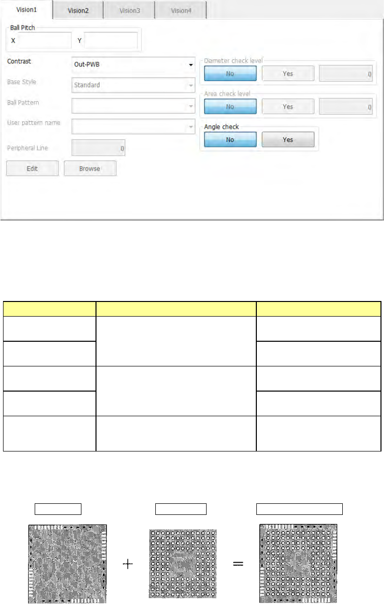
When you select "All balls," the recognition pattern can be set by setting "Base style"
and "Ball pattern."
Base Style + Ball Pattern → Recognition pattern
Part 1 Basic Operation Chapter 4 Creating a Production Program
4-98
③ Base style
Set a base style (mark arrangement pattern).
Combination of a base style and a ball pattern is to be used as a recognition pattern.
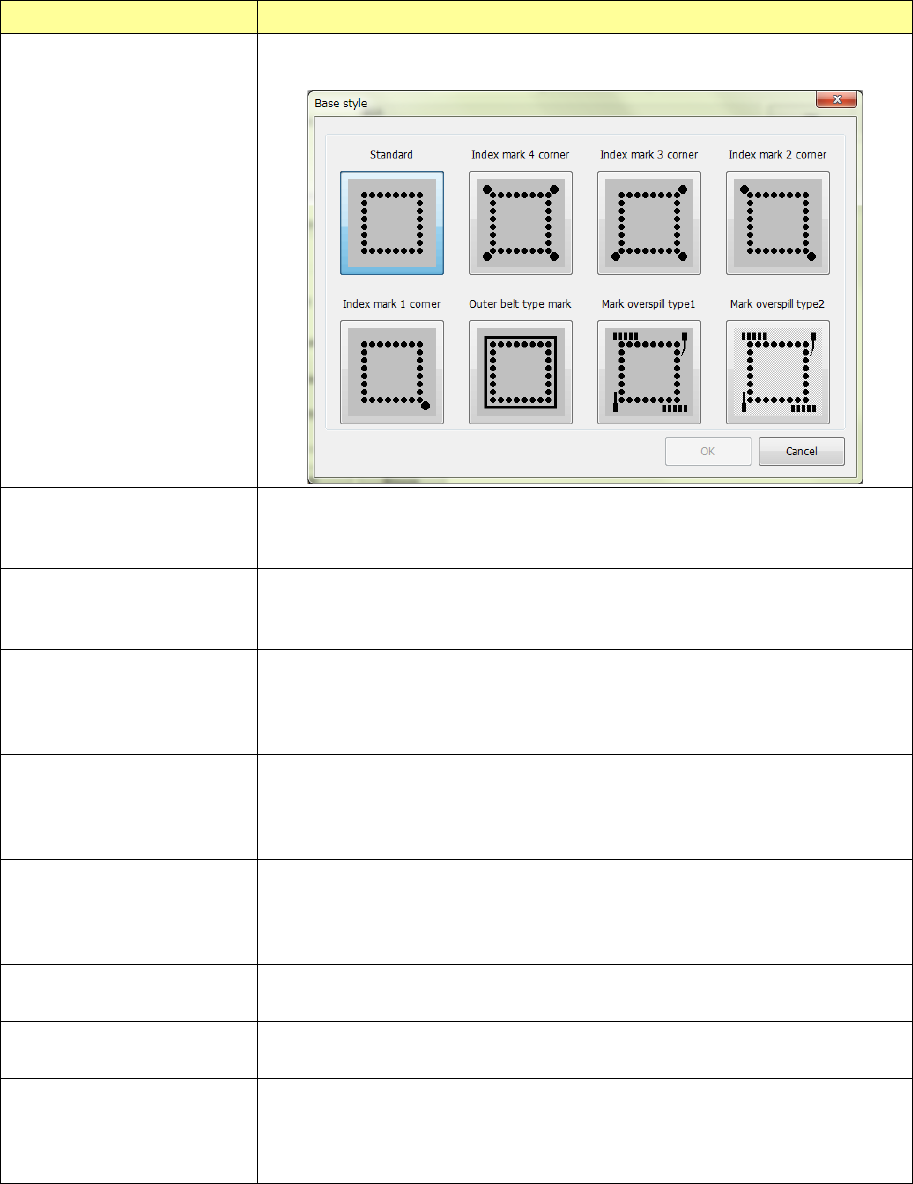
Base style selection item Contents
Browse
This item allows you to select a base style from the “Standard” type to the
“Mark overspill type” from the sample diagram.
Standard There is not anything other than balls on the outer periphery of the package.
Conventional BGA with a narrow pitch and small balls
Index balls may be on lattices.
Index marks 4 corners There is not anything other than balls and index balls on the outer periphery of
the package and the index balls exist outside of lattices. Index balls are
arranged on 4 corners outside lattices.
Index marks 3 corners There is not anything other than balls and index balls on the outer periphery of
the package and the index balls exist outside of lattices. Index balls are
arranged on 3 corners outside lattices. (The status where there is no index ball
on the upper left corner is specified as 0°.)
Index marks 2 corners There is not anything other than balls and index balls on the outer periphery of
the package and the index balls exist outside of lattices. Index balls are
arranged on 2 corners outside lattices. (It is supposed to be 0 degrees when
an index ball exists in the upper left and lower right corners.)
Index mark 1 corner There is not anything other than balls and index balls on the outer periphery of
the package and the index balls exist outside of lattices. Index balls are
arranged on 1 corner outside lattices. (It is supposed to as 0 degree when an
index ball exists in the lower right corner.)
Outer belt type mark Materials with a density level close to balls are arranged in a belt form on the
outer periphery of the package.
Mark overspill type 1 Materials other than balls are scattered over the outer periphery of the
package. (Normally, select this.)
Mark overspill type 2 Materials other than balls are scattered over the outer periphery of the
package.
(Select this when there is a narrow and long base style whose diameter is the
same as that of a ball to be recognized.)
Part 1 Basic Operation Chapter 4 Creating a Production Program
4-99
④ Ball Pattern
Set a ball arrangement pattern here.
Combination of a base style and a ball pattern is used as a recognition pattern.
Choice
Remarks
Standard BGA
Peripheral BGA
Staggered std. BGA (More out) You can select this only when the pitch is from 2.00 mm to 3.00 mm.
Staggered per. BGA (More out)
You can select this only when the pitch is from 2.00 mm to 3.00 mm.
Staggered std. BGA (Fewer out)
You can select this only when the pitch is from 2.00 mm to 3.00 mm.
Staggered per. BGA (Fewer out)
You can select this only when the pitch is from 2.00 mm to 3.00 mm.
⑤ User pattern name
If you already created and registered a ball pattern(s) with the BGA editor, which is
described later, you can select a registered pattern here.
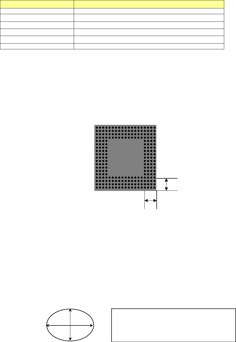
⑥ Peripheral Line
When you select “Peripheral BGA,” “Staggered per. BGA (More out)” or “Staggered per.
BGA (Fewer out) as a ball pattern, set the number of lines on which balls are located by
counting them from the outer periphery.
When you select any other type of ball pattern, “0” is displayed here, and this item is
disabled.
Example: When “4” is set as the Peripheral Line
⑦ Diameter check level
⑧ Variant check level
When “All balls-PWB” or “All balls-Ceramic” is selected as the “Contrast,” you can specify
whether to check the diameter/variant or not and the threshold value.
The input range of the level is from 1 to 100 %. The default value is 50 %.
When you specify the stricter check (by setting the smaller value), the rate of error becomes
higher.
- Diameter check level: The system measures the length and the width of each ball, and if
either of them exceeds (falls below) the set value, the system handles this as a recognition
error. It is recommended to specify 40 % or a bigger value.
- Variant check level: When the number of counted pixels per area of a ball that is
converted from the entered ball diameter is less than or greater than the set value, the
system handles this as a recognition error. It is recommended to specify 45 % or a bigger
value.
4
4
If either “1-(H/R)” or “1-(V/R)” is greater or less than the
set value (%) on the supposition that the entered
diameter value is “R,” the system will regard it as an
error.
H
V