RS-1_instruction manual.pdf - 第559页
Part 1 B asic O peration Chapter 4 Cr eating a Produc tion Progra m 4- 224 (4) Operation during tr acking of a component pi ck - up p osi tion While the sy stem is track ing a component pick - up position , you c an use …
Part 1 Basic Operation Chapter 4 Creating a Production Program
4-223
6) Zoom
When you check the <Zoom> check button, you can enlarge the image shot with the camera
and superimposed on the screen if you enable the option “Enable digital zoom teaching” on
the “Operation option” screen.
When the length of the longer side of the component outer dimensions is 2.26 mm or more,
the system does not enlarge any image shot with a camera regardless of the setting of the
“Operation option” screen.
When “the placement angle” + “the circuit angle” is not any of 0, 90, 180 and 270 degrees,
the system does not enlarge any image either.
The system switches the enlargement factors as shown below depending on the outer
dimensions of a component:
• 4x zoom (The option “Enable 4x zoom” has to be checked on the “Operation option”
screen.)
When the length of the longer side of a component is from 1.11 mm to 2.25 mm: the
displayed image is doubled in size.
When the dimension of the longer side is from 0.01 mm to 1.10 mm, the displayed image
is quadrupled in size.
• Without 4x zoom
When the length of the longer side of a component is from 0.01 mm to 2.25 mm, the
displayed image is doubled in size.
7) Feed
This button feeds a feeder displayed at the “Slot” field.
8) AUTO
This button makes a camera recognize the cavity and automatically teach it so that a
component can be located at the center position.
9) OK/CANCEL
These buttons are enabled only after you manually enter coordinates or change them by
teaching operation.
When you press the <OK> button, the system memorizes the XY coordinates in the
placement data.
If you do not want to memorize the changed values, press the <CANCEL> button.
When you press the <CANCEL> button, the coordinates changed by teaching operation are
reset to the previous values.
Part 1 Basic Operation Chapter 4 Creating a Production Program
4-224
(4) Operation during tracking of a component pick-up position
While the system is tracking a component pick-up position, you can use the following switches
and/or buttons to control the tracking operation.
Operation Operation panel Button on the screen
Start of tracking <START> switch <EXEC> button
Stop of tracking <STOP> switch
Moving to the previous point <Prev> button
Moving to the next point <STOP> switch <Next> button
End of tracking Press the <STOP> switch
when the system stops.
Press the <CANCEL> button
when the camera stops.
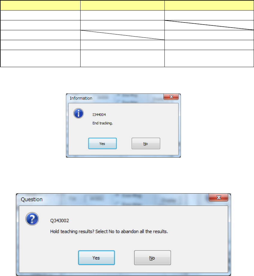
When the tracking is completed with operation steps described above, the following message
appears.
When you press <No> in the above dialog box, the screen returns to the “Pick position tracking”
screen. When you press <Yes>, the following message appears, prompting you to save the
teaching results.
When you press <No>, the coordinate values, which have been taught during the tracking
operation, are discarded and returned to the coordinate values before starting the tracking, and
then the tracking is completed.
When you select [Yes], the coordinate value is updated by the pickup coordinates changed during
tracking, and the tracking is finished.
Part 1 Basic Operation Chapter 4 Creating a Production Program
4-225
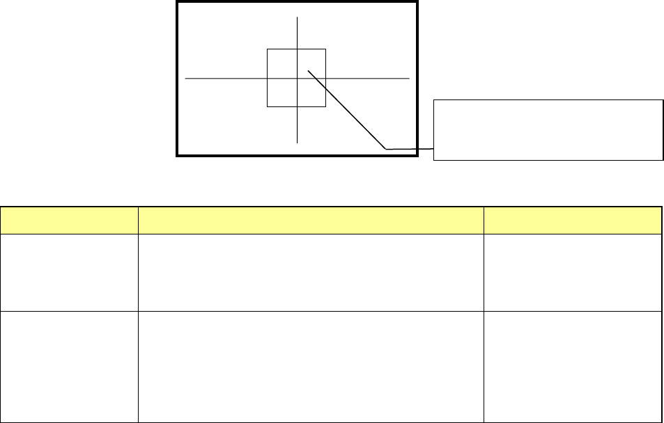
(5) Displaying the superimpose screen
1) Tracking a component pick-up position
When the system is tracking a component pick-up position, it displays the crossed lines
indicating the center of the component pick-up position and the window frame appropriate
for the size and placement angle of a component on the superimpose screen. According to
the setting of the Operation option, the circle whose radius is equal to the length of the
longer side of the component is displayed at the center of the screen.
Display of the center and four corners of a component varies depending on the component
size as described below.
Component size
Four corners of a component
Center of a component
Component whose
shorter side is 4.5
mm or less
The window frame displayed on the screen indicates four
corners of a component.
A placement position whose angle was set is displayed by
rotating the window frame itself.
Center of the point at which
lines are crossed.
Other components
(large components)
The camera moves to each set of coordinates of four
corners: [TOP-L], [TOP-R], [BTM-R] and [BTM-L] in this
order. For a component placement position whose angle
was set, the camera moves to the coordinates obtained by
rotating four corners.
After the camera moves to
all of four corners,
[CENTER] is displayed on
the monitor. The camera
moves to the center of a
component.
(6) Teaching coordinates during tracking
If the tracked coordinates are different from the actual ones, you can teach the component
pick-up coordinates with the teaching function.
<Procedure>
① Move the cursor to the X, Y or Z coordinate.
② Press the <Teaching> button of the function bar to open the “Teaching” screen.
Teach the coordinates and press the <OK> button to obtain the taught coordinates
data.
③ To make the obtained coordinate values valid, press the <OK> button.
To reset the coordinates to the original ones, press the <CANCEL> button.
(7) Measuring the component pick-up height with the HMS while the camera is tracking a
component pick-up position
When you press the <HMS> button while the camera is tracking a component pick-up
position, the system can measure the component pick-up height. The “Pick position
tracking” screen is switched to the “Pick height tracking” screen.
The HMS always measures the component pick-up height on the “Pick height tracking”
screen. When the measured value is correct, press the <Z Set> button to reflect it to the
set value.
To return to the tracking operation with a camera, press the <CAMERA> button.
The center of a component or the frame
indicating four corners of the component is
displayed on the screen.