RS-1_instruction manual.pdf - 第342页
Part 1 B asic O peration Chapter 4 Cr eating a Produc tion Progra m 4-7 4.3.2 Procedure for cr eating a production program A production program cons is t s of fou r items: “P WB data, ” “ Plac ement data, ” “ Com ponent …
Part 1 Basic Operation Chapter 4 Creating a Production Program
4-6
4.3 Preparation of a Production Program
To produce a PWB, prepare the production program data.
To prepare or edit the production program data, start up the Program Editor.
4.3.1 Starting up the Program Editor
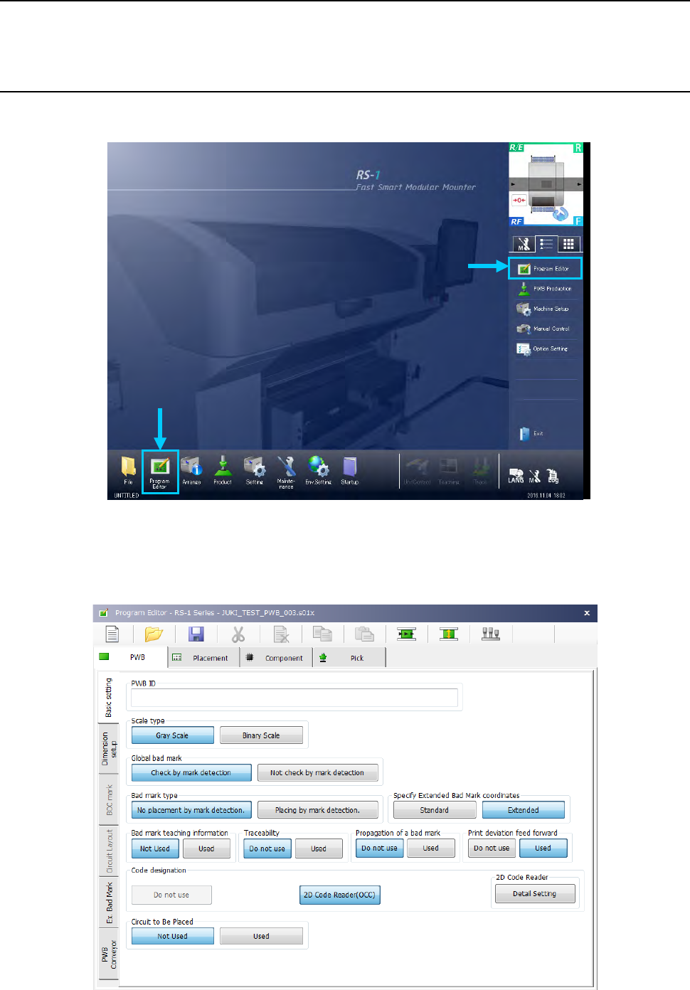
Start up the Program Editor on the following desktop screen.
Select the “Program Editor” button in the Operation area or that in the Information area.
When you start up the Program Editor, the name of the loaded program is displayed on the right
side of the title bar, and the PWB ID is displayed on the status bar.
When you try to create a new production program, “UNTITLED” is displayed as the program name,
and the “PWB ID” field becomes blank.
Part 1 Basic Operation Chapter 4 Creating a Production Program
4-7
4.3.2 Procedure for creating a production program
A production program consists of four items: “PWB data,” “Placement data,” “Component data”
and “Pick data,” and the tabs displayed on the upper section of the screen correspond to these
types of data respectively.
Create a production program in the following order: “PWB data” -> “Placement data” ->
“Component data” -> “Pick data.”
Note that only half-sized alphanumeric characters can be entered with a soft keyboard.
Type of data Description
PWB This covers overall PWB data such as PWB outer dimensions and the coordinates of Board
Offset Correction (BOC) mark position.
Placement This covers coordinates of the placement position, component names to be placed and others.
Component The data including component dimensions and packaging style required for laser and vision
centering is handled.
Pick This covers the data on positions of components supplied by a tape feeder, tray, etc.
You cannot open the next data screen until you completely create the data you are
supposed to create first: for example, you cannot open the “Placement” data screen if
you have not created “PWB data” completely.
4.3.3 PWB data
PWB data consists of five items: “Basic setting,” “Dimension setup,” “BOC mark,” “Circuit layout,”
“PWB Conveyor” and “Ex. Bad Mark”.
Setting Overview
Basic setting Enter the basic PWB configuration here
Dimension setup
Enter the detailed dimensions of a PWB. This item can be selected only when “Multi-circuit
non-matrix” is set in “Dimensions setting.”
BOC mark Enter the coordinates of BOC marks.
Circuit layout
Enter the position and angle of a circuit. You can enter these items only if you select
“Non-matrix circuit” as the “PWB configuration” on the “Basic setting” screen.
Ex. Bad Mark
Enter the coordinates of a bad mark on each circuit when you are to use an extended bad
mark.
PWB Conveyor Make the detailed settings of the conveyor and the support table
Part 1 Basic Operation Chapter 4 Creating a Production Program
4-8
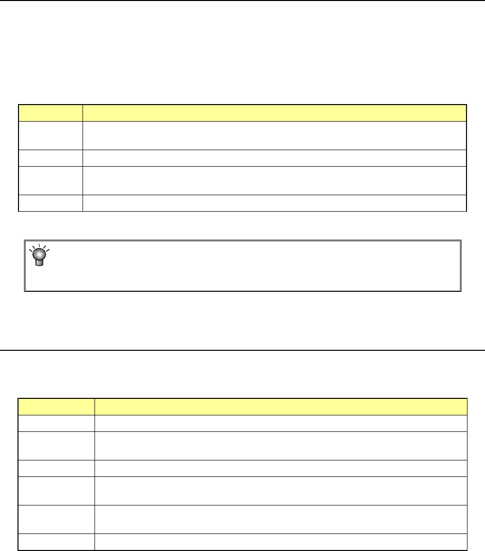
4.3.3.1 Basic setting
When you select the “Basic setting” tab displayed on the left side of the screen, each item of the
“Basic setting” tab is displayed on the screen.
Enter or select the appropriate items according to a PWB to be produced.
In the PWB data, the following 1) to 11) are set.
1) PWB ID
Enter a “comment” that elaborates on the PWB name.
Up to 60 alphanumeric characters/symbols can be entered.
As this PWB ID is displayed during production program creation and production, we
recommend you to describe an easy-to-understand name.
You can omit the PWB ID.
2) Scale type
For mark (BOC mark and area mark) recognition for the whole PWB, the following 2
methods are selectable.
Selection should be made according to the condition of the BOC mark.
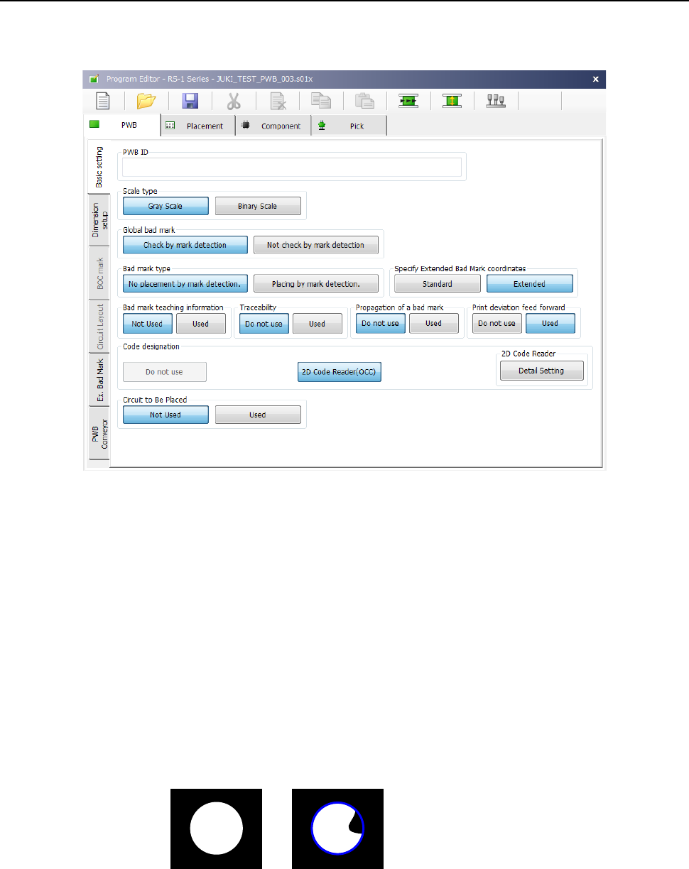
♦ Gray Scale: With all the information obtained by OCC, mark recognition is
performed by matching method.
This method is available even in a high noise environment because much information
is used. Normally select this option.
* If a certain level of coincidence is obtained though the external shape is partially missing,
the recognition result is regarded as OK.
♦ Binary Scale: If an error occur during the gray scale recognition, select binary scale
recognition. If the edge of the mark is not shot clearly, the accuracy will be lower than
that of the gray scale recognition method.
Registration mark
Recognition mark