RS-1_instruction manual.pdf - 第862页
Pa r t 2 Det ai l ed Des c r i pti on o f Ea c h Fu nc ti on Chapte r 1 1 S el f - diagnosis Func ti on 11 -4 Che ck F un cti on Consu mable component r ep la cement not ifyi ng f unc ti o n On the b asi s of the us ing …
Part 2 Detailed Description of Each Function Chapter 11 Self-diagnosis Function
11-3
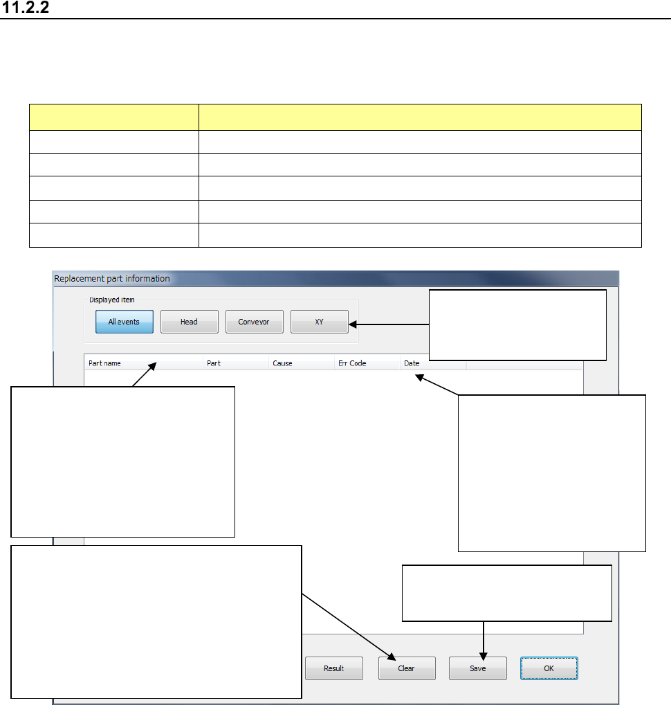
Detailed display of self-diagnosis information
The detailed display of self-diagnosis information is a screen that displays a list of replacement
component information. Regarding the replacement component information, the following
contents are displayed.
Display item Contents
Part name Name of the component to be replaced (formal name on the drawing)
Portion Portions when there are multiple positions
Reason for replacement Reason for required replacement (time, etc.)
Error code Error code resulting in required replacement
Date of occurrence Date of required replacement
A display item is further
specified by each button
of “Display item.”
(Sorting function)
When an item line is selected,
part name sorting is executed.
(Ascending order)
If you select once again in the
ascending order sorting, it is
returned to the original status.
Reasons for occurrence of
replacement
(Time) Replacement is
now required by time
monitoring.
(Error) Replacement is
judged by error code.
The replacement component
information is saved in a file.
Item clear button A line of replacement
component is selected and cleared.
(When this clearing operation is performed,
the data is saved into the replacement
record file.)
User level: Valid at the manager’s authority
or higher
Part 2 Detailed Description of Each Function Chapter 11 Self-diagnosis Function
11-4
Check Function
Consumable component replacement notifying function
On the basis of the using status of consumable components, this function notifies the replacement
time according to each replacement standard.
The replacement time is judged by the standard (time, operation count, moving distance, etc.) set
for each component.
For judgment of the replacement time, the self-diagnosis information to be newly installed is used.
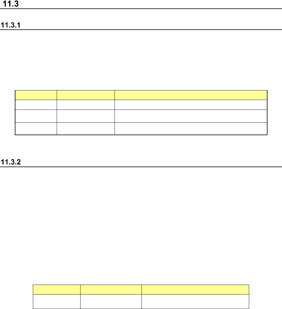
The intended consumable components and check items are shown below.
Unit Component Check item
Head Filter Time
Conveyor Conveyor belt Count (conveyor)
XY XY robot cable (*1) Signal
(*1) This is checked at a return-to-origin and a flag is put in the self-diagnosis data.
Error occurrence monitoring function
The error occurrence monitoring function monitors the frequency of error occurrence in relation to
errors that may result from a device failure.
The error occurrence monitoring function is realized by the following functions.
(1) When an error occurs, it is checked whether the error occurred in the same unit within one
month (30 days).
(2) When the same error occurs more frequently than the specified level in (1), the maintenance
of the corresponding unit is judged to be necessary.
(3) This function is managed by the data table in which the corresponding unit is associated with
the error number.
The objects to be monitored in relation to the frequency of error occurrence are as follows.
Unit Portion Contents
Head LNC120-8 LNC120 connection failure

Part 2 Detailed Description of Each Function Chapter 11 Self-diagnosis Function
11-5
Individual check function
The individual check function checks the device for each operation item,
The items to be checked by the individual check function are shown in the following table.
No.
Individual check function group
Description
1 CAL block mark stain check
Checks whether the CAL block mark is covered with a jig or
component so that an error may not be caused to the coordinate
system at a return-to-origin.
2 Filter stain check
Checks whether a failure occurs due to anchoring of the ejector by
turning on/off the vacuum of the head several times.
3 Set VCS cleanliness Check Runs a VCS cleanliness check, and then determines the result.
4 Head Offset
Assembling position of each head for the OCC
Assembling angle between the laser alignment unit and the main
unit
5 Laser/sensor height Height of the laser/sensor viewed from the topside of a board
6 Vacuum calibration Executes a vacuum measurement.
7 VCS offset
Assembling position/assembling angle of a standard/high-resolution
VCS
8
VCS multi-recognition offset
Assembling position of each nozzle center against the VCS (54mm)
9
ATC Slide Plate Open/ Close
Check
Checks the open/close time of the ATC slide plate to find a nozzle
replacement fault.
(1) Immediately after a start
When you sleet [Maintenance] → [Self-diagnosis function] in the desktop screen menu, the
initial screen of self-diagnosis appears.
(2) End of self-diagnosis
When you select “Exit” of the information area or the Exit button at the right of the title bar, the
application is terminated.