RS-1_instruction manual.pdf - 第112页
Part 1 B asic O peration Chapter 2 Pr oduction 2-1 Chapter 2 Product ion 2.1 Flo wchart for product ion This chapt er describe s the operati ons marked wi th t he numbers f rom 2 to 5, and 9 to 12 in the flowchart be l o…
Part 1 Basic Operation Chapter 1 Overview of the Machine
1-93
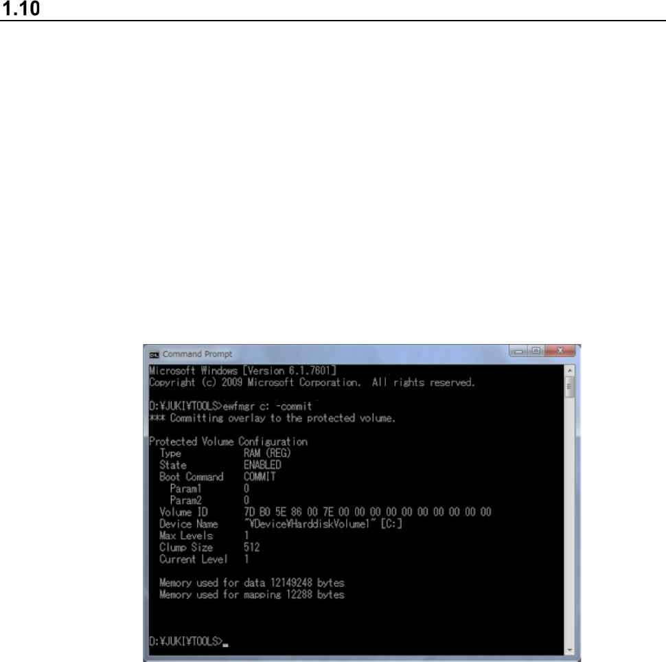
Updating the Drive C
The machine uses the Enhanced Write Filter (EWF) to create the drive C, which Windows uses as
ROM, in order to protect the OS.
Therefore, to change the information of the OS, update the dive C by following the instructions
below.
Be sure to perform this operation after you add the function requiring a driver such as a printer or
after you set up the network.
If you happen to turn off the machine even though you have not performed this operation, the
information you set is erased.
(1) Start up the command prompt.
(Start up the command prompt from Explorer, by executing
“C:¥Windows¥System32¥cmd.exe”).
(2) Enter “ewfmgr C: -commit” on the console window (DOS screen).
The screen like the one shown below appears.
(3) Shut down Windows, and then start up the machine again.
Information emulated with the main memory during the shutdown process is written onto the
drive C.
Part 1 Basic Operation Chapter 2 Production
2-1
Chapter 2 Production
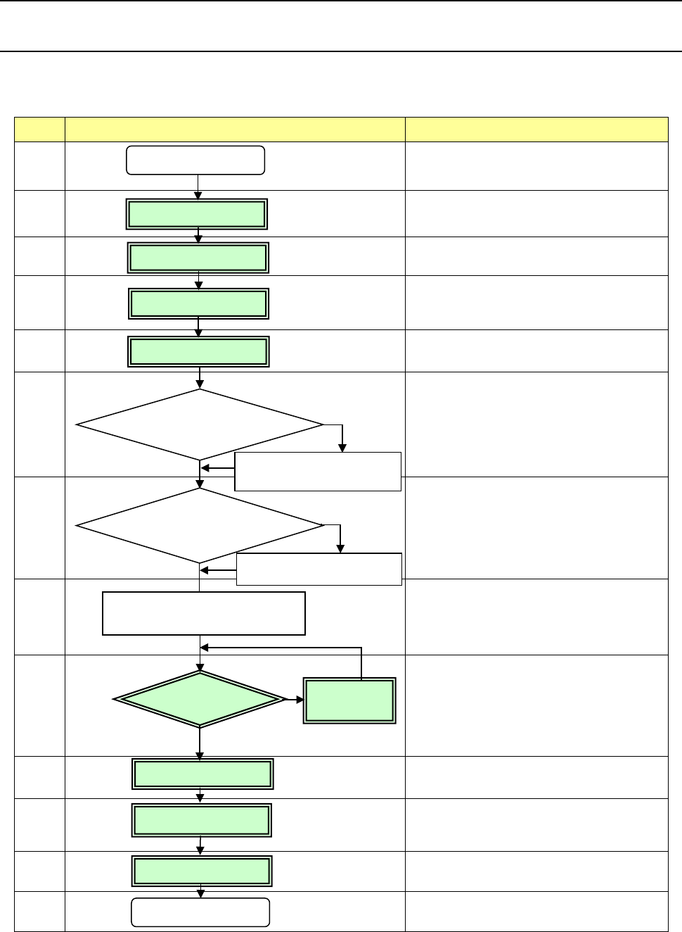
2.1 Flowchart for production
This chapter describes the operations marked with the numbers from 2 to 5, and 9 to 12 in the
flowchart below.
No Flowchart Comment
1
Perform routine inspection including an
ATC-related check.
2
Check the main air pressure (0.5 MPa).
3
Check to see if there is no foreign substance
inside the machine before production.
4
Be sure to warm up the system after holidays or in
cold climates (it takes approximately 10 minutes).
5
6
Change the settings on the “Machine setup” menu
if you clean the nozzle and you have to change
the initial setup after you perform the daily
inspection or set a PWB.
(See Chapter 8 “Machine Setup.”)
7
See Chapter 5 “Database.”
8
9
If any problem occurs during PWB placement:
for example, the PWB position is shifted from the
regulated position or the centering function fails,
correct the production program on the “Program
Editor” menu. You can correct a part of
component data on the “Production” menu also.
10
11
12
13
Perform the daily inspection periodically.
(See Chapter 3 “Daily Maintenance.”)
No
Yes
Change the desired settings
on the Machine setup menu.
Create component data on
the “Database” menu.
Power ON
Inspection of system
Origin return
Warm-up
PWB setting
Create the component
database?
Production
Power OFF
No
PWB placement
confirmation
No problem
Daily inspection
Correct the
program.
Problem
Yes
Creation/Edition of
your production program
Change the machine
setup conditions?
End of production
Part 1 Basic Operation Chapter 2 Production
2-2
2.2 Overview
Use the created production program to check that a PWB is placed correctly and produce PWBs.
After creating a new program, perform a trial PWB production before actually producing PWBs in
order to check the PWB placement/pick-up coordinates and perform the final check of the program.
Production mode
The following four production modes are available during production:
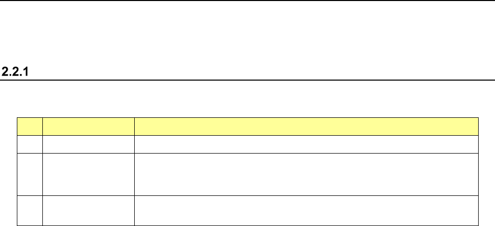
No. Production mode Description
1 PWB production Specifies the number of PWBs you plan to produce and produces PWBs actually.
2 Trial Performs a trial PWB production.
You can select the PWB pick-up position tracking function or PWB placement
position tracking function that is to be performed after placement. *1
3 Dry run Checks the PWB pick-up/placement process without using any component.
You can select the PWB pick-up/placement position tracking function. *1
*1 See Section 4.5.6.4 “Component placement position” and Section 4.5.6.5 “Component pick-up
position/component pick-up height.”
The system allows you to specify the requirements for producing PWBs, performing a trial PWB
production, or executing the dry run operation in each mode above.