RS-1_instruction manual.pdf - 第718页
Part 2 D etaile d Descript ion of E ach Functi on Chapter 8 Machine Set up 8- 10 Conveyor W hen you sele ct “ Conveyor , ” the following scre en appears. When you clic k each ta b, “ Head, ” “ Base, ” “ Conv eyor ” or “ …

Part 2 Detailed Description of Each Function Chapter 8 Machine Setup
8-9
No. Unit Production operation
1
IC Collection Belt
(Front/Rear)
This function is just deleted, and placement is executed.
2
Feeder Float Detector
(Front/Rear)
This function is just deleted, and placement is executed.
3
Feeder trolley
(Front/Rear)
This function is just deleted, and placement is executed.
4
Cutter
(Front/Rear)
This function is just deleted, and placement is executed.
5
Area select
(Front/Rear)
This function is just deleted, and placement is executed.
6 Auto-refresh bank type
This function is just deleted, and placement is executed.
7 Mini signal light This function is just deleted, and placement is executed.
8 Component verification
No verify operation is performed even if Component
verification is specified.
9 Coplanarity
The machine places a component on a board without
running a coplanarity check even though the component
coplanarity is specified.
10 Load Cell
The load nozzle check is not run even though a load control
nozzle is used.
11
Do not change related
value when Component
data is edited.
If you set this function to ON, the number of items whose
default values have to be set again due to change of one
data item is minimized when you edit the Component data
already set.
(2) How to set
1) Specify a device to be used by check button.
When a check mark is attached, this means a “Use” setting. If no check mark is
attached, this means a “No use” setting.
2) It is impossible to select a unit that is not set as an option (unit indicated in light
characters).
3) Enter a value in the “Cutter Interval” field from a keyboard directly. Note that you
cannot enter any value in this field if the cutter is set to be unused.
Part 2 Detailed Description of Each Function Chapter 8 Machine Setup
8-10
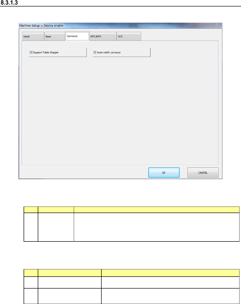
Conveyor
When you select “Conveyor,” the following screen appears.
When you click each tab, “Head,” “Base,” “Conveyor” or “VCS” can be specified.
(1) Setting item
No.
Item
Description
1
Conveyor
Specify the use of no use of the unit
When you set “No use” in this item, pick placement can be executed
without changing the production program data even if a unit failure
occurs.
The following table shows whether placement is actually performed or not when the above
function is required for the production program to complete placement.
No.
Unit
Production operation
1 Support Table Stopper The function is just deleted, and placement is executed.
2 Auto-width conveyor
Although the “Auto-width conveyor” function is just deleted,
the machine places a component on a board.
(2) Setting method
1) Specify a device unit to be used by using the check button.
When a check mark is attached, this means a “Use” setting. If no check mark is
attached, this means a “No use” setting.
Part 2 Detailed Description of Each Function Chapter 8 Machine Setup
8-11
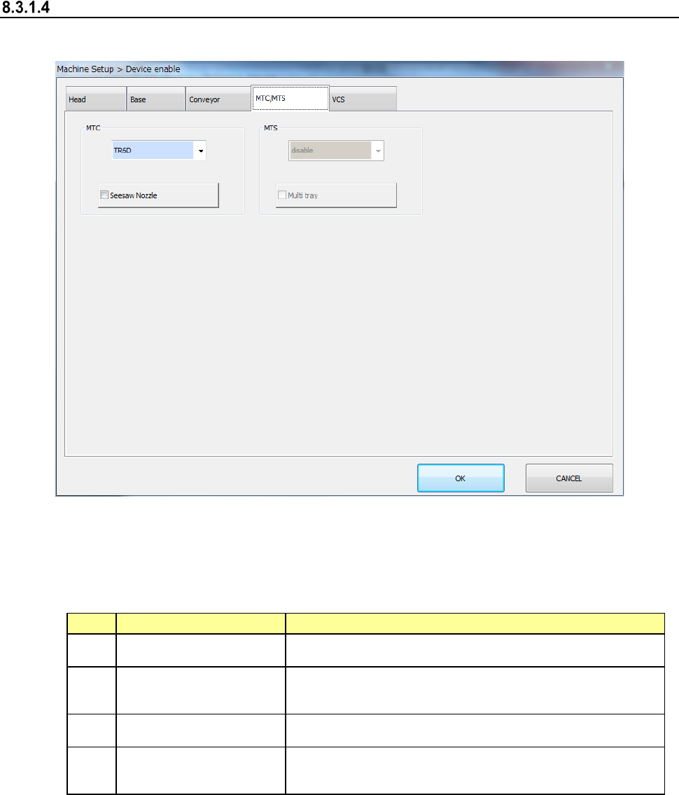
MTC/MTS
When you select “MTC/MTS,” the following screen appears.
When you click each tab, you can specify each of “Head,” “Base,” “Conveyor,” “MTS” and “VCS.”
(1) Setting items
The use setting of MTS is performed.
No.
Item
Description
1 MTC Set the use/no use of the unit and its type.
2 Seesaw Nozzle
When MTC is not unused, this item can be set.
Set whether to use a seesaw nozzle or not.
3 MTS Set the use/no use of the unit and its type.
4 Multi-tray
When MTS is not unused, this item can be set.
Set the use/no use of the multi-tray.
(2) How to set
1) Select a model name in the combo box.
2) Specify the Use/No use of the multi-tray by check button.
When a check mark is attached, this means a “Use” setting. If no check mark is
attached, this means a “No use” setting.