RS-1_instruction manual.pdf - 第402页
Part 1 B asic O peration Chapter 4 Cr eating a Produc tion Progra m 4- 67 ⑥ Multi - recog nition This functi on is descr ibed as follo ws. As the V CS with a field - of - view of 54 m m captur es images of u p to four co…
Part 1 Basic Operation Chapter 4 Creating a Production Program
4-66
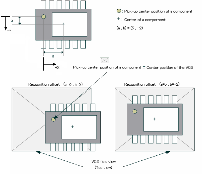
③ Recog. Offset
The system moves the pick-up center position of a component (normally the center of a
component) to the center position of the VCS to center the component with the VCS.
However, since the system cannot pick up the center of a component such as an MCM
(Multi Chip Module) and the component position may be located outside the VCS field view
range, it may not be able to center the component with the VCS. In this case, enter offset
values (a, b) as shown below to ensure normal recognition.
Example: Data entry
④ Gripper nozzle data
Set this item as described in “1) Laser centering.”
⑤ S-VCS
Specify whether to recognize a component with an S-VCS or not.
VCS field of view (top view)
Part 1 Basic Operation Chapter 4 Creating a Production Program
4-67
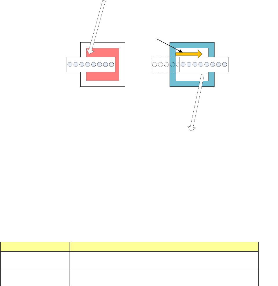
⑥ Multi-recognition
This function is described as follows. As the VCS with a field-of-view of 54 mm captures
images of up to four components and recognizes them, the XY-axis movement distance and
the number of image capturing times during VCS recognition operation are minimized.
Additionally, as the light control is optimized, the exposure time of the VCS camera is
shortened to a level that is 1/6 or less of the conventional exposure time and the placement
tact of the vision recognition is improved from the conventional S-VCS.
The S-VCS can perform the recognition only with the same light within one cycle, but the
multi-recognition can perform the recognition with different light settings using nozzles 1 to 4
and nozzles 5 to 8.
The following describes the component data conditions for the multi-recognition.
1. Vision components with a component size of □ 3 mm to □ 14 mm (Pickup offset is
considered.)
2. Boss height 0.00 mm
3. Recognition center offset (0.00 mm, 0.00 mm)
4. VCS selection is a field-of-view of 54 mm.
5. Lights other than transmission light
6. VCS focus height is 0.00 mm.
7. Batch recognition
8. The direction of a BGA component is not inspected.
When the conditions shown above are satisfied, "Used" or "Not used" can be set.
Used or not Contents
Used
(Default)
Performs the multi-recognition.
Not used
Does not perform the multi-recognition even when there are
components applicable to the multi-recognition.
① Moves to the right head
recognition position from
the pickup position.
⑤ Moves to the
placement position
from the left head
recognition position.
② Right head recognition
with the reflection light
③
Moves to the left head
recognition position
from the right head
recognition position.
④ Left head recognition
with the blue side light
Part 1 Basic Operation Chapter 4 Creating a Production Program
4-68
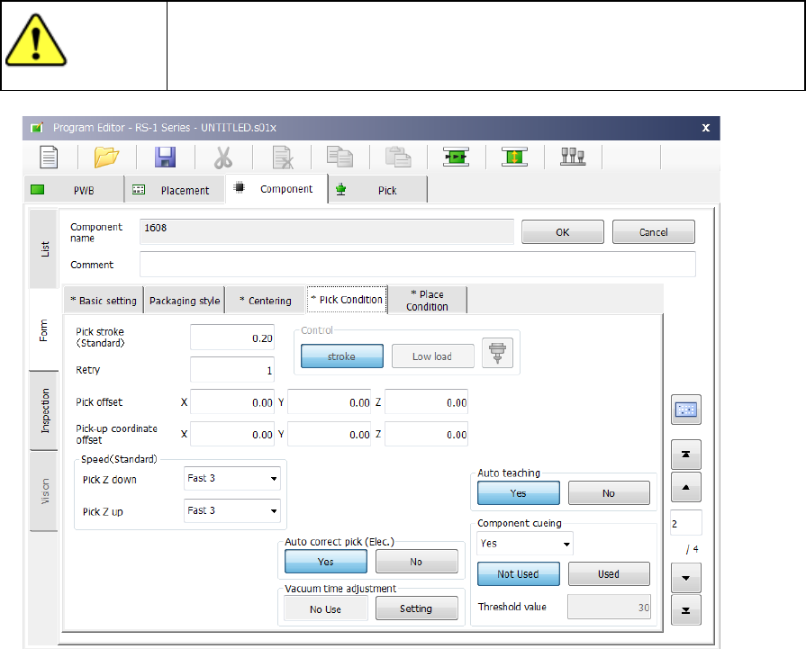
(4) Pick Condition
Pick conditions are setting items for pickup and the default values are applied. Accordingly,
they do not need to be changed. If pickup cannot be performed in the default value status,
change the settings.
CAUTION
If you change any of the basic settings after changing any value on the
“Pick Condition” tab, some values are reset to their defaults on the “Pick
Condition” tab.
1) Picking stroke:
Specify the distance for pushing a component during component pick-up.
If you set “0” here, the nozzle may not reach a component and may not pick up the
component, or a chip rise error may occur due to the variation of component heights. In
such a case, enter the larger value (that is, by entering a positive value) so that the nozzle
can reach a component.
The initial value is “0.2 mm” (0 mm for a 0603 or 0402 component).
2) Retry:
Set the number of times the system will pick up a component again if a component pick-up
error occurs during production.
If a retry over error occurs during PWB production, the signal light flashes in yellow to notify
you of the error.