RS-1_instruction manual.pdf - 第391页
Part 1 B asic O peration Chapter 4 Cr eating a Produc tion Progra m 4- 56 3) Tr ay input m ethod ① Pil ot Posi tion Enter the dist ance fr om the tray out side to the cent er positi on (X, Y) of the first tray component.…
Part 1 Basic Operation Chapter 4 Creating a Production Program
4-55
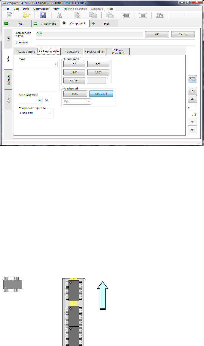
2) How to enter data when you select “Stick” as the “Packaging style”
① Type
Select a type of a stick feeder.
② Feed wait time
Specify the ratio of the actual waiting time to the waiting time (specified for each type) until
the next component becomes able to be picked up after a component is picked in percent
figures.
The initial value is 100 %.
③ Supply angle
Enter a value indicating how much the component package on the stick feeder inclines
against the JUKI’s component supply angle “0 degrees.”
See “JUKI's definition of the component supply angle” of “(1) How to enter data when you
select “Tape” as the “Packaging style”” of “(2) Packaging style” under Section 4.3.5.2 for
details.
When you select the <Other> button, enter the angle in the edit field (0°to 359.9875°).
④ Component reject to
Set the component discarding method to be applied in a case where centering results in a
recognition error or lead floating inspection results in an error.
See “Component reject to” of “(1) How to enter data when you select “Tape” as the
“Packaging style”” of “(2) Packaging style” under Section 4.3.5.2 for details.
How to feed
Angle definition 0° Supply angle 270°
Part 1 Basic Operation Chapter 4 Creating a Production Program
4-56
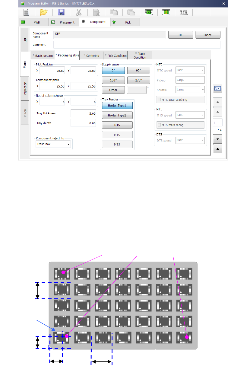
3) Tray input method
① Pilot Position
Enter the distance from the tray outside to the center position (X, Y) of the first tray
component.
② Pitch between components
Enter the pitch between components (Pitch X, Pitch Y).
③ No. of columns/rows
Enter the number of components (Xn, Yn) in the lateral direction and the longitudinal
direction.
After the pickup data supply position is determined, the coordinates of 3 positions of the tray
are displayed in the pickup data. (X
1
, Y
1
to X
3
, Y
3
)
First component position X
First component
position Y
First
component
Pitch X
Pitch Y
(
X
2
,Y
2
)
(
X
1
Y
1
)
(
X
3
Y
3
)
Part 1 Basic Operation Chapter 4 Creating a Production Program
4-57
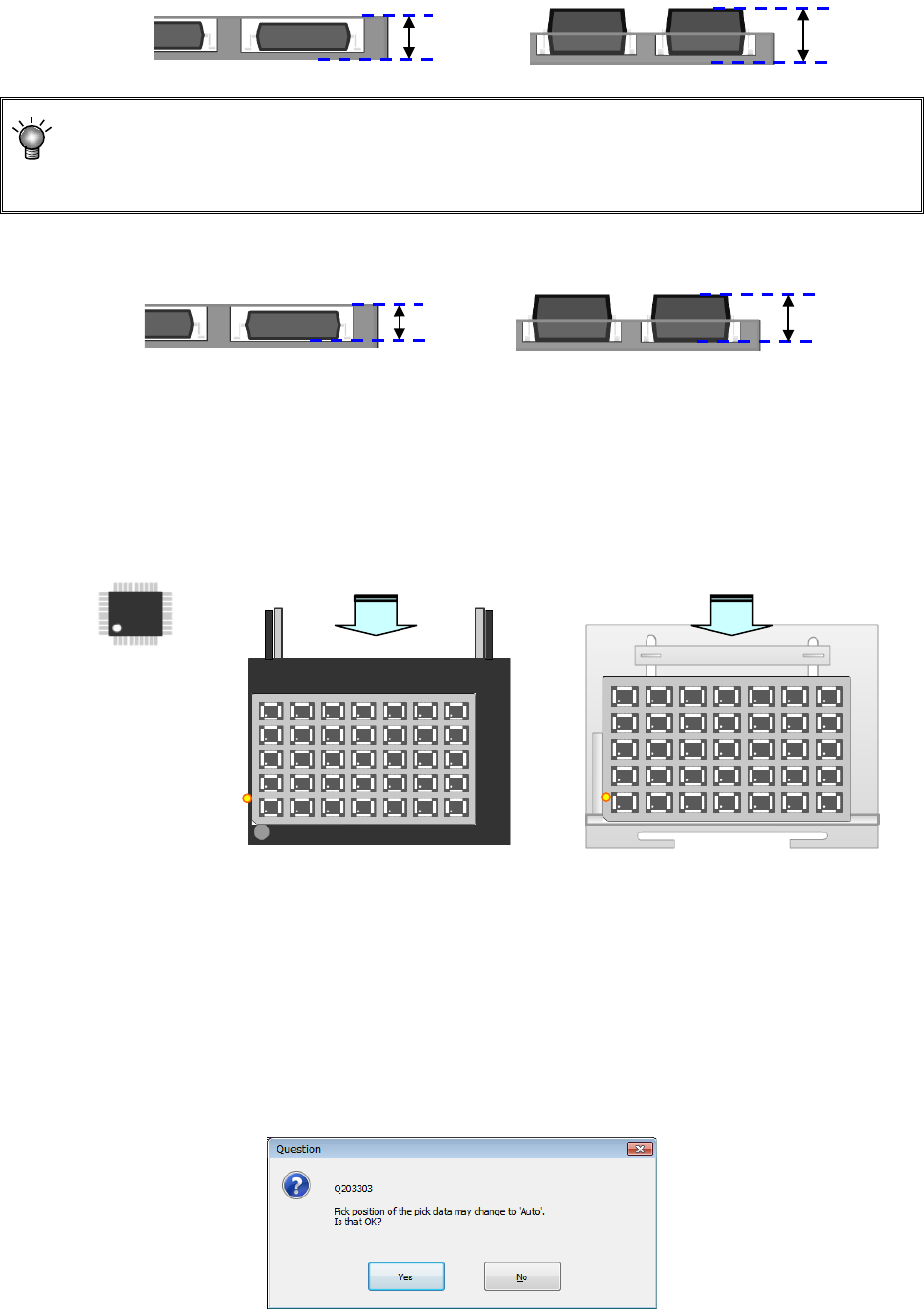
④ Tray thickness
Enter the tray thickness from the tray bottom to the top surface including components.
When the thickness “T” of a tray of an MTC/MTS exceeds 9 mm, any tray base cannot be set
on the stage immediately above the stage on which this tray is set. When the thickness “T” of
a tray exceeds 23 mm, any tray base cannot be set on the stage two levels higher than the
stage on which this tray is set either. The maximum thickness “T” of a tray is 36 mm.
⑤ Tray depth
Enter the depth of the tray.
⑥ Supply angle
Enter an angle at which the component packing style on the stick feeder is inclined to the
JUKI component supply angle of 0°
For details, refer to "4.3.5.2(2) Packaging style 1) How to enter data when you select “Tape”
the “Packaging style”, * JUKI component feed angle definition."
When you select “Other,” enter the angle in the edit field. (0º to 359.9875º)
⑦ Component reject to
Set the component discarding method for a case where centering results in a recognition
error or lead floating inspection results in an error. For details, refer to "4.3.5.2(2) Packaging
style 1). How to enter data when you select “Tape” the “Packaging style”, Component
discarding."
⑧ Tray Feeder
Select a tray feeder among “Holder,” “DTS,” “MTC” and “MTS.”
If you change the setting of a tray feeder of a component for which two or more records of
pick data have been entered, the following message appears on the screen.
Angle definition 0°
供給角度 180°
供給角度 0°
Supply angle 0°
Supply angle 180°
Supply from the rear bank
Supply to the MTC, or MTS
Tray depth
Tray depth
Tray
thickness “T”
Tray
thickness “T”