RS-1_instruction manual.pdf - 第978页
Part 2 D etaile d Descript ion of E ach Functi on Chapter 12 Handling th e Optional Device s 12 - 94 (4) Measurable rang e The measura ble range is 1 mm or less. If the area indicated below e xceeds 1 mm, an err or occur…
Part 2 Detailed Description of Each Function Chapter 12 Handling the Optional Devices
12-93
12.14.2.3 Criteria for a check
■ Colinearity check (available for a lead component only)
The machine uses a value set in the “Tolerance” field of the “Coplanarity check” on the
“Component” data screen invoked with the Program Editor to check upward/downward
bending of leads on each side.
◇ A position to be checked is the center of the side of a board on which each lead is set.
■ Coplanarity check
The machine uses a value set in the “Tolerance” field of the “Coplanarity check” on the
“Component” data screen invoked with the Program Editor to check upward/downward
bending of leads.
12.14.3 Overview of the specifications
(1) Applicable components
QFP, SOP, BGA and connector
* These components are applicable only if they are recognized with a VCS.
For a ball component (BGA), the machine measures only a ball component whose
“Contrast” is set to “All balls-PWB” or “All balls-Ceramic” on the “Vision 1” tab. Note that a
component whose data is created as a general-purpose vision component is not
applicable.
(2) Resolution and precision
① Resolution: 1μm
② Precision (3σ) : ± 15 μm
This unit may not correctly judge a component whose terminal is damaged due to contact
with a contact probe. It may not be able to correctly judge a lead component whose
terminal is not rectangle-shaped or whose side to be measured is not flat either.
(3) Component dimensions
Item Dimensions
Lead
component
Pitch
0.4 mm or more
Lead width
0.2 mm or more
Lead length
0.3 mm or more
Component size
48 mm x 150 mm or less
Ball
component
Pitch
0.8 mm or more
Ball diameter
0.4 mm or more
Component size
48 mm x 150 mm or less
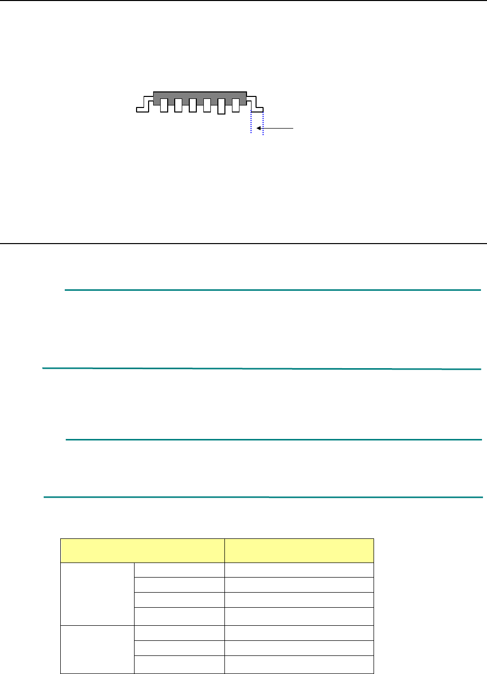
Scanning position

Part 2 Detailed Description of Each Function Chapter 12 Handling the Optional Devices
12-94
(4) Measurable range
The measurable range is 1 mm or less. If the area indicated below exceeds 1 mm, an error
occurs.
(5) Retry of measurement
You can set how many times the machine will measure a component again if a measurement
error occurs.
(See Section 8.3.6.8 “Coplanarity.”)
(6) Parameters to be entered for measurement
① Tolerance, which is to determine coplanarity during measurement
② Electrode size: width and length (only for a lead component)
③ Measurement Height Offset
④ Lead Offset
⑤ Exposure Time
(7) Output of measurement results
① Determination if the result is accepted or not as compared to the preset value
② Information on the height of all terminals and determination if the height is accepted or
not
(8) Laser strength
Laser: Class 3B (IEC60825-1:2007), visible radiation
Maximum output: 100 mW
Wavelength: 600 – 700 nm
1mm
Part 2 Detailed Description of Each Function Chapter 12 Handling the Optional Devices
12-95
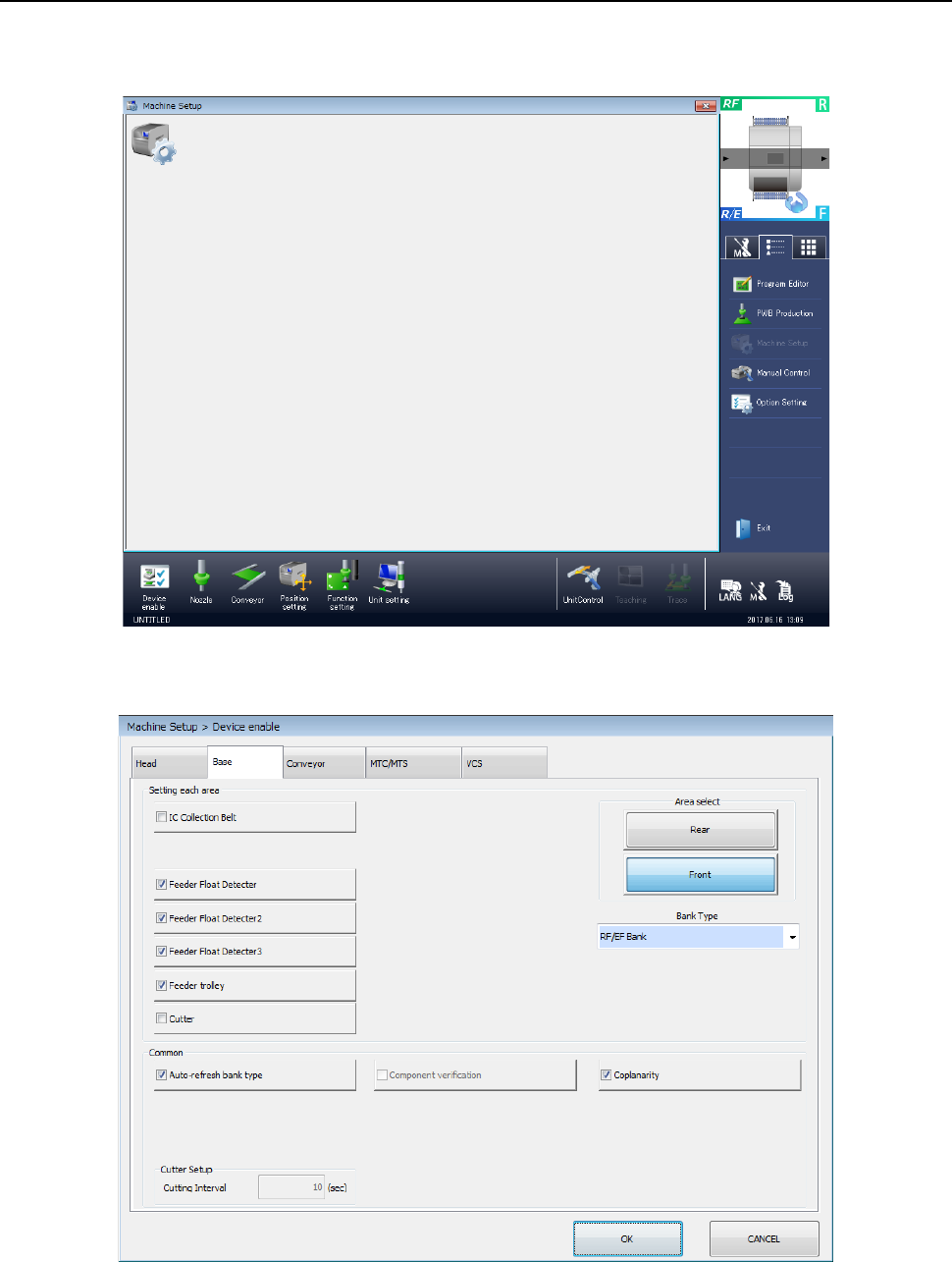
12.14.4 Machine Setup
To run a coplanarity check, you have to make the necessary settings on the “Machine Setup”
screen.
Start up the “Machine Setup” utility.
1) Select the “Device enable” icon from the “Machine Setup” screen menu, and then the “Base”
tab on the displayed screen.
Place a checkmark in the “Coplanarity” check box.
When you place a check mark in this check box, the coplanarity unit is enabled.