RS-1_instruction manual.pdf - 第458页
Part 1 B asic O peration Chapter 4 Cr eating a Produc tion Progra m 4- 123 (4 ) Lane When you us e a stick feeder , select the lane n umber . The lane numb ers are assigned from 1 when vie wed from t he left on both the …
Part 1 Basic Operation Chapter 4 Creating a Production Program
4-122
4.3.6.2 Creating Pick data
(1) Angle
Specify the component picking angle.
When “Auto” is selected for the menu item “Side,” you do not have to enter this item. In this case,
“*” is displayed on the “List” screen, while this menu item itself is dimmed on the “Form” screen.
When “Front” or “Rear” is selected for the menu item “Side” and some value is specified in the
“Position” field, you can change the value already set for this item. The angle set on the
"Component" data screen is set here by default.
To change the value, move the input focus to the “Angle” field, and then enter the desired value.
Even though you enter a value into this “Angle” field on the “Pick” data screen, the
corresponding angle is not changed on the “Component” data screen or database.
(2) Side
Specify on which side to set a feeder, on the front side or on the rear side.
“Auto” is selected in this field as the initial value.
When “Auto” is selected, the Optimization function assigns a feeder.
Auto
The Optimization function assigns a feeder.
Front
Components are supplied on the front bank.
Rear
Components are supplied on the rear bank
When “Tray” is selected as the “Package,” you cannot select “Front.”
To assign an electric feeder (EF) to the machine, you have to select the side on which the electric
bank (RF/EF) is attached.
You have to specify this “Side” menu item together with the next item “Position.”
When you select two or more pick data records to change the setting of the menu item “Side,” you
can select “Auto” only.
8mm-width-1mm-feed pitch and 12mm-2mm-feed pitch can be selected only for the electric feeder
(RF).
To use the electric feeder (EF) for the electric bank (RF), an attachment (option) is needed.
(3) Position
Enter the position for mounting a component supply unit.
Component supply unit Number to be specified
Tape feeder
Stick feeder
Number of a feeder mounting hole to which the fixing pin at the front-end of the
machine is inserted.
Tray holder Number of a feeder mounting hole indicated with the mounting marker of a tray
holder
DTS/MTC/MTS Number of the level on which a tray is stored
You cannot specify another type of component supply unit on the position whose
number was already specified for one type of component supply unit.
Example: If you specify “Front 10” in this field for an RF 12-mm tape feeder, you
cannot specify any other feeder at the positions from Front 10 to 11.
Part 1 Basic Operation Chapter 4 Creating a Production Program
4-123
(4) Lane
When you use a stick feeder, select the lane number.
The lane numbers are assigned from 1 when viewed from the left on both the front side and the
rear side.
Only one lane is to be used on the current supply device.
When you use a DTS, select the stage on which a tray component is stored.
The system automatically calculates the component pick-up position from the DTS based on the
tray information of the Component data to show it.
The top side is the first stage, while the bottom side is the second stage.
(5) Feeder type (You have to specify this menu item for a tray, an electric tape feeder or a stick
feeder.)
Select a type of a tray an electric tape feeder or a stick feeder.
Note that the contents set in the component data of a stick feeder or a tray are displayed here. To
change any of the contents, do it on the “Component” data screen.
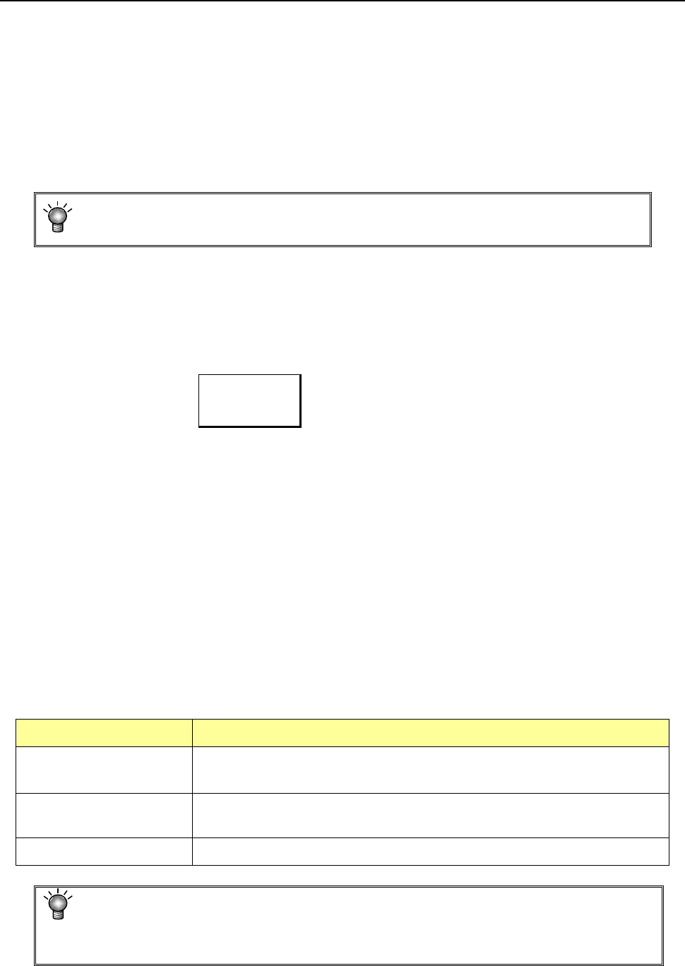
• Tray holder
Tray holders are classified into "Type 1 (full specification)" and "Type 2 (half specification)."
Tray holder (Type 1) Tray holder (Type 2)
* When installing a tray holder, check it at the position of the ▲POSITION mark.
● For electric bank (RF) :
When the electric bank (RF) is used, only the electric tape feeder (RF) can be selected for
the feeder type.
● For electric bank (RF/EF) :
When the electric bank (RF/EF) is used, the electric tape feeder (RF) or electric tape feeder
(EF) can be selected for the feeder type. The default setting is the electric tape feeder (RF).
To mount the electric tape feeder (EF), an optional attachment is needed.
When the electric feeder (EF) is mounted on the electric bank (RF/EF) using the
attachment, the pickup accuracy is not guaranteed.
Part 1 Basic Operation Chapter 4 Creating a Production Program
4-124
(6) Pick position
Specify the X, Y and Z coordinates of the component pick-up position here. When you enter data
into the “Side” and “Position” fields, the system automatically calculates and displays these
coordinates. Make fine adjustments of these coordinates with teaching operation.
CAUTION
To avoid a risk of injury, do not put your hands inside the machine nor
move your face or head close the machine while the system is performing
a teaching operation.
If the feeder bank is never recognized (for example, immediately after the
devices of the machine return to their home positions or the bank moves
down then up), the head moves across the feeder bank when you perform
a teaching operation. Do not place your hand or head in the machine, nor
move your hand or face close to the machine.
When you use an HMS, use caution for preventing laser beam from getting
into your eyes directly or after reflecting by a mirror.
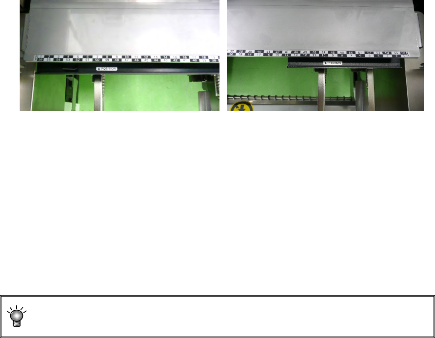
You can enter only the “X1” and “Y1” fields for a tape feeder or stick feeder.
For a tray, you have to perform the teaching operation for three positions (X1Y1, X2Y2 and X3Y3
as shown in the figure below) since the head moves to each component position and pick up each
one from a tray. Note that you do not have to enter any data in the “Z” field in case of an MTC
since a component is picked up inside the MTC.
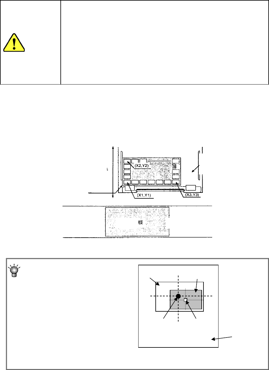
Specify the center of the frame within
which a component is located instead
of the center of a component as the
XY coordinates.
* If you specify an incorrect value in the “X,” “Y” or “Z” field, a tombstone error or
pick-up error may tend to occur.
Frame
Component
Center of
the frame
Center of a
component
Feeder unit
Putting in/out
PWB
MTS, MTC, DTS or tray
holder
Transport path
Machine front
Press the tray against here