RS-1_instruction manual.pdf - 第928页
Part 2 D etaile d Descript ion of E ach Functi on Chapter 12 Handling th e Optional Device s 12 - 44 12.7.3 Function “Change of standby pos ition of a short substrate” The RS -1 /1R is equipped wi th t wo W AIT sen sors …

Part 2 Detailed Description of Each Function Chapter 12 Handling the Optional Devices
12-43
12.7.2.4 Limitations on the supported long-sized board
- The machine cannot track a component placement of a long-sized board with a camera
during Try Run or Dry Run operation.
- The machine can track a component placement position of a long-sized board as long as the
corresponding head can move to its coordinates when the [Placement tracking] command is
executed from the “Support” menu.
The machine cannot track any coordinates to which no head can move due to the board
clamping condition.
- When you optimize a production program for a long-sized board by selecting the optimization
option “Assign in optimized order” and optimizing the program, the machine cannot perform
optimization with taking two clamping operations into consideration. Select the option
“Assign in input order of Production Program File” to optimize a program.
- If component placement positions of a circuits are arranged over two areas: area clamped for
the first time and area for the second time, set a bad mark position in the first component
placement area.
- When an MTC is used with the machine, the maximum X-dimension of a board that can be
transported is limited.
Part 2 Detailed Description of Each Function Chapter 12 Handling the Optional Devices
12-44
12.7.3 Function “Change of standby position of a short substrate”
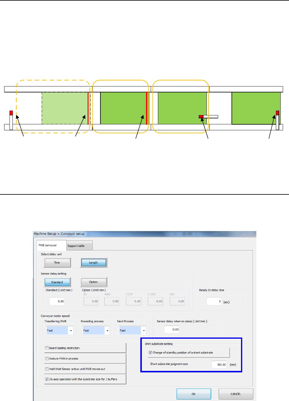
The RS-1/1R is equipped with two WAIT sensors for waiting for a board to be loaded to the
machine. When you change the standby position of a short-sized board (whose X-dimension is
300 mm or less), you can improve the board change cycle time.
When this function is disabled or when the X-dimension of a board exceeds the value set as the
“Short substrate judgment size” of the “Machine Setup” screen, the standby position is located
above the “WAIT sensor” as shown in the figure below.
* When a short-sized board waits above the WAIT2 sensor, the machine does not load the next
board onto the WAIT sensor.
12.7.3.1 How to set (on the “Machine Setup” screen)
Select the [Conveyor setup] command, and then the “PWB conveyor” tab from the “Machine Setup”
screen to check the “Short substrate setting.”
See Section 8.3.3.1 “Conveyor setup” for how to set this item.
IN sensor
WAIT sensor
WAIT2 sensor
OUT sensor
STOP sensor
Normal board
standby position
Short-sized board
standby position
Production position
Part 2 Detailed Description of Each Function Chapter 12 Handling the Optional Devices
12-45
12.7.4 ZA-axis operation with the substrate size for 3 buffers
When the machine transports a board in 3-buffer mode, this function adjusts the ZA-axis height to
the highest one of positions at which components have been already placed in the same manner
as 1-buffer mode. This allows the machine to always produce a PWB at the optimal ZA height.
When there is a board on the OUT buffer in this case, the machine controls the ZA-axis operation
according to the board size so that any head will not come in contact with components already
placed on the board.
12.7.4.1 Supported board size
The machine supports the board size that can be handled in 3 buffer mode.
Note that the conveyor extension option decides the applicable board size and the ZA-axis
operable timing as shown in the table below.
Conveyor extension option
Available ZA-axis moving-down timing
OUT sensor is set to ON. OUT sensor is set to OFF.
No conveyor extension (standard) 50mm – 150 mm
More than 150 mm, and less than or
equal to 360 mm
Downstream side extension by 150 mm
(option)
50mm – 300 mm
More than 300 mm, and less than or
equal to 360 mm
Downstream side extension by 250 mm
(option)
50mm – 360 mm -
Both sides extension by 150 mm
(option)
50mm – 300 mm
More than 300 mm, and less than or
equal to 500 mm
Both sides extension by 250 mm
(option)
50mm – 400 mm
More than 400 mm, and less than or
equal to 600 mm
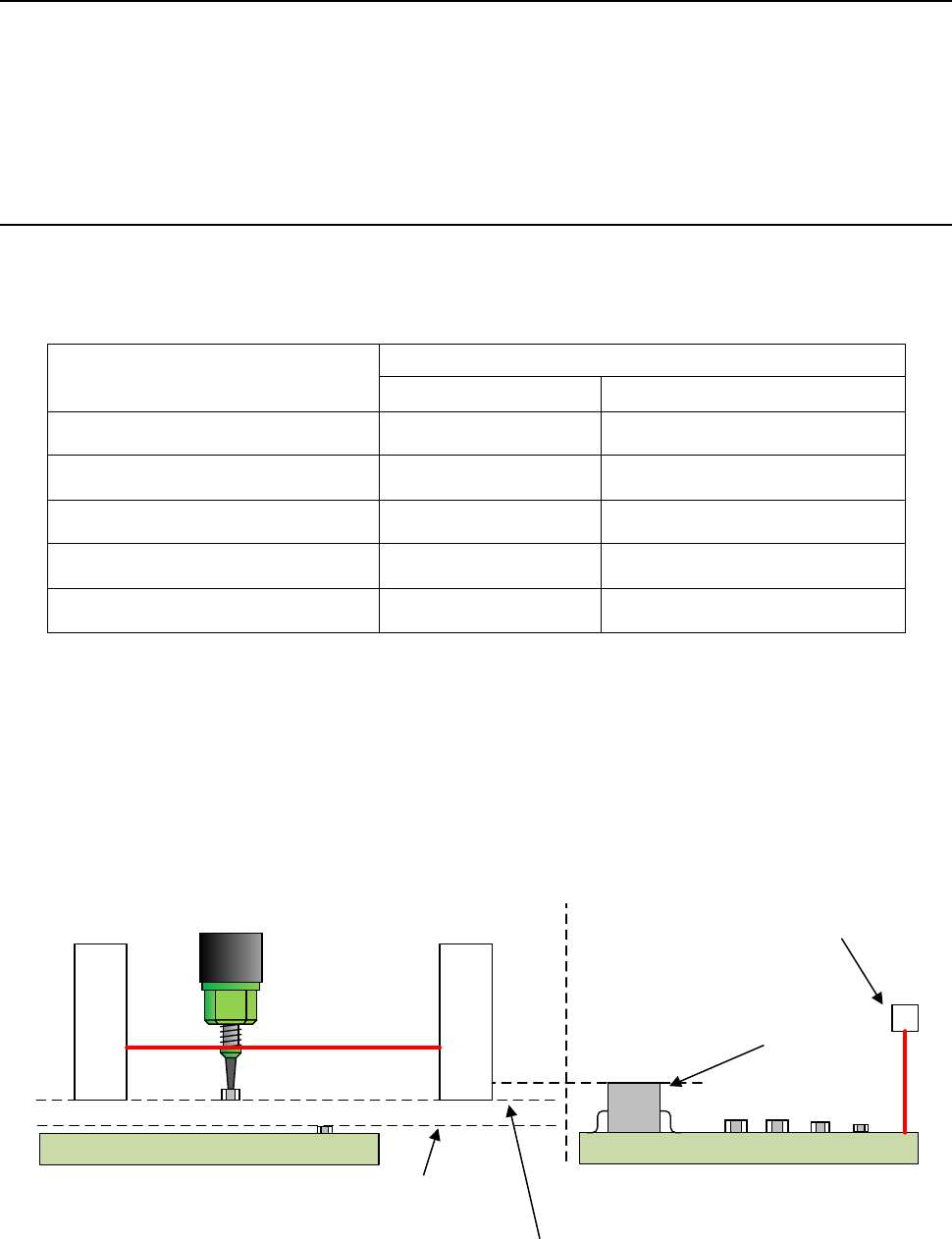
(1) Board that allows the ZA-axis to move down when the OUT sensor is set to ON
If a board is shorter than the head movable limit when another board on which a component
has been already placed waits for itself to be ejected above the OUT sensor, the ZA-axis can
move down even though there is a standby board (the OUT sensor is set to ON), and the
ZA-axis can operate according to the highest one of the positions at which components have
been already placed.
Head movable limit
OUT sensor
Board on which a component is already
placed and waits for ejection
Board on which a
component is being
placed
Maximum height of a
component already
placed on the board
Height of the bottom side of the LNC120
XY-axes movable height
Maximum height of a
component already
placed on the board that
waits for ejection