RS-1_instruction manual.pdf - 第702页
Part 2 D etaile d Descript ion of E ach Functi on Chapter 7 Operation Option 7- 27 7.5.2 Inspection ope ration When you pres s the < Inspection operat ion> button, t he “ inspect ion operation set ting screen ” app…
Part 2 Detailed Description of Each Function Chapter 7 Operation Option
7-26
No. Menu item
Description
Status Operation and detailed explanation
4
Pick position offset check
Specify the pick position offset check function.
After a component pickup, the offset value from the center of the nozzle
is judged by laser recognition. Thus, a pick position shift is detected.
5
Check nozzle alignment
in pick
Specify the execution of the nozzle alignment check function. Precision priority
is set in the machine setup, this item can be specified.
The nozzle alignment check function becomes effective. For
high-density placement, a pick position shift error occurs if the nozzle
protrudes from the component at a component pick.
6
Component mis-release
check function
Specify the execution of the component take-back check function.
The component mis-release check function becomes effective.
7
Properties checked
Specify an item to be checked.
You can select this check box only when the coplanarity unit is enabled with the
MS Parameter utility and the ratio of the colinearity is not 0.
Only Colinearity checked
The machine runs a colinearity check only.
Colinearity and
Coplanarity check
The machine runs both a colinearity check and a
coplanarity check.
Part 2 Detailed Description of Each Function Chapter 7 Operation Option
7-27
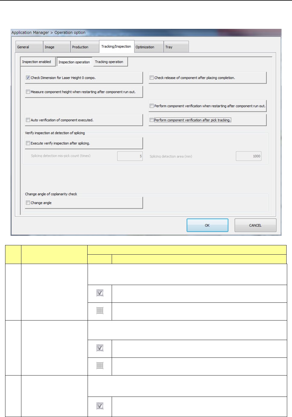
7.5.2 Inspection operation
When you press the <Inspection operation> button, the “inspection operation setting screen”
appears.
No. Menu item
Description
Status Operation and detailed explanation
1
Check release of
component after placing
completion
Specify the execution of a nozzle separation check of a component when the
component is placed.
Make sure by laser that no component is left in the nozzle when the
Z-axis goes up after component placement.
The [Component release check] setting of component data is ignored
and no check is made.
2
Check dimension for
laser height 0 compo.
Change the pick check height for components with a laser height of 0 or more to
prevent a detection error by nozzle.
For components for which the laser height is set to 0 or more, a pick
check by laser is made at 0.1 mm or less from the end of the nozzle.
A pick check is made by laser at the laser height regardless of the set
value of laser height.
3
Measure component
height when restarting
after component run-out
Specify the component height measurement at a start after occurrence of no
components. Unless the HMS unit is set, this item cannot be selected.
Component height measurement is executed at a start after
occurrence of no components.
Part 2 Detailed Description of Each Function Chapter 7 Operation Option
7-28
No. Menu item
Description
Status Operation and detailed explanation
4
Perform component
verification when
restarting after
component run-out
Specify the verify inspection at a start after occurrence of no components.
Unless the CVS unit is set, this item cannot be selected.
Verify inspection is executed at a start after occurrence of no
components.
5
Auto verification of
component executed
Specify the execution of verify inspection for automation-oriented components at
a start of production. Unless the CVS unit is set, this item cannot be selected.
Automatic verify inspection is executed at a start of production.
6
Perform component
verification after pick
tracking.
Specify whether to perform verify inspection after pick position tracking. Unless
the CVS unit is set, this item cannot be selected.
Verify inspection is executed after pick position tracking.
7
Execute verify inspection
after splicing.
Specify whether to run a verify check for the first component of a new reel when a
spliced point is detected.
You cannot select this menu item when any CVS device is not set.
Runs a verify check when a spliced point is detected or when the first
component of a new reel is picked up.
Splicing detection
mis-pick count (times)
Set the number of component pick-up mistakes for
detecting a spliced point.
Splicing detection area
(mm)
Set the length of a component reel for detecting the
spliced point.
8 Change angle
Specify the inspection angle for a coplanarity check.
You cannot select this check box when change of the coplanarity inspection
angle is not allowed by the MSP.
The system runs a coplanarity check at the following angles depending
on a component type:
SOP, TSOP or connector: 90 or 270 degrees: the angle is decided
according to which angle is closer to the component placement angle.
TSOP: 0 or 180 degrees: the angle is decided according to which
angle is closer to the component placement angle.
QFP or PQFP (BQFP): 45, 135, 225 or 315 degrees: the angle is
decided according to which angle is the closest to the component
placement angle.
Runs a coplanarity check at the inspection angle specified in
Component data.