RS-1_instruction manual.pdf - 第222页
Part 1 B asic O peration Chapter 2 Pr oduction 2- 111 Verify Current check (1) S electi ng a compon ent 1) “Component of inspectio n” and “Com ponent selection” Data on the comp onent appears in these fiel ds. Names of c…
Part 1 Basic Operation Chapter 2 Production
2-110
Verify check
Overview
Select the [Support] command from the “Product” menu, and then the [Verify Current check]
command or the [Verify All check] command from the “Support” menu.
The system attaches an actual component on the head and compares the resistance value,
capacity and polarity stored in a production program (Component data) with those of the attached
component to inspect them. Be sure to perform this type of check after setting the feeders on the
feeder bank.
Verify check type
Description
Single check mode
When you select the [Verify Current check] command from the “Support” menu, the system
performs a verify check for the specified component only. In addition, the system
separately checks a component at which it detected an error on Continuous Check mode.
Continuous check
mode
When you select the [Verify All check] command from the “Support” menu, the system
checks components that satisfy your requirements among all components whose data is
stored in the production program.
- In Single check mode, the system can check a component that failed to pass this check
for some reason.
Operations
(1) Head used to pickup a component
The system does not perform measurement with two or more heads at the same time. The
head used to pick up a component is automatically selected.
(2) Returning/discarding a component after checking it
The system returns some checked components onto their original positions, and discards
other ones depending on their packaging style as shown in Table below.
Where to discard a component is determined according to the setting of “Compo Reject to” on
the Component data screen. Since a component whose size is 1 mm or less may stand on
its side or may be turned upside down when it is returned to the original position, the system
displays the “Question” screen to ask you how it should handle a component.
Note that you cannot pick up a component manually.
Packaging style Condition
Returning a
component
Discarding a
component
Tape
The short side length of the external size is 1 mm or less.
“Question” screen *1, *3
The short side length of the external size is 1 mm or more.
○ ○
*2, *3
Holder
―
○ ○
*2
MTC
―
○ ○
*2
MTS
―
○ ○
*2
*1 The system displays the screen to ask you whether to return a component or discard it. When
the system enters Continuous measurement mode, it displays this “Question” screen before
continuous measurement.
*2 The system discards a component when you select “IC collection belt” or “Protect” in the menu
item “Comp reject to.”
*3 A component is discarded when the feeder type is a stick feeder.
(3) Selecting a feeder used to pick up a component
If two or more feeders are assigned to the same type of components on the Pick data screen,
the system starts picking up components from one whose data was entered first of all by
default. Only in Single check mode, you can change the feeder used to pick up a component
intentionally.
(4) Changing the coordinates of a component pick-up position
If a component cannot be picked up normally, manually enter the coordinates of a component
pick-up position or teach them to change them.
Part 1 Basic Operation Chapter 2 Production
2-111
Verify Current check
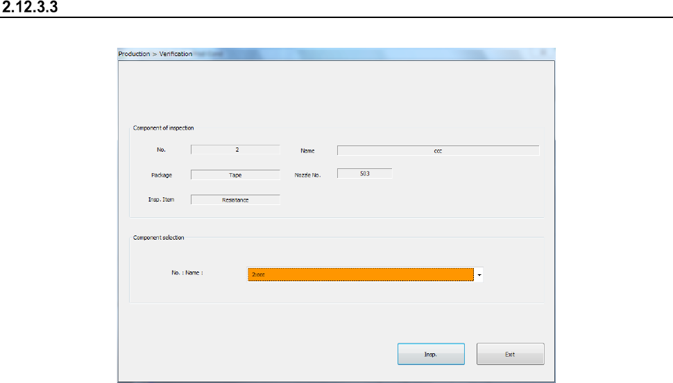
(1) Selecting a component
1) “Component of inspection” and “Component selection”
Data on the component appears in these fields. Names of components whose
“Component verification” setting is “Yes” on the “Component” data screen are displayed as
the list in the “Name” combo box. Select a component to be checked here.
Part 1 Basic Operation Chapter 2 Production
2-112
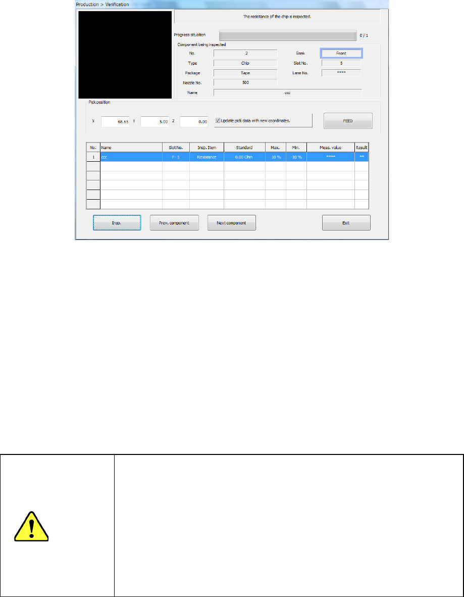
(2) Execution of a check
1) Progress situation
The current progress situation is shown with the progress bar.
2) Component being inspected
Data on a component you selected to check appears here.
3) Pickup position
Data on the component pick-up position appears here. You can change the pick-up position
to that of the previous alternate component or the next alternate component also.
4) Verification result
The following data on the component being currently selected appears on the screen:
component name (“Name”), fixing hole (“Slot No.”), inspection item (“Insp. Item”), standard
value (“Standard”), upper limit of the tolerant value (“Max.”), lower limit of the tolerant value
(“Min.”), measured value (“Meas. value”) and check result (“Result”). After the component is
checked, the check result is displayed in the “Meas. value” field.
5) <Insp.> button
This button performs a verify check for the specified component alone.
CAUTION
Immediately after you press the <Insp.> button, the head starts moving
and the system starts inspection.
To avoid injuries, do not put your hands inside the machine or keep
your face or head away from the machine.
Before pressing the < Insp.> button, check to see if there is no one who
is working the internal parts of the machine.
Before pressing the < Insp.> button, check to see if there is no one who
is near the machine and may be injured.
Before pressing the < Insp.> button, check to see if there is no obstacle
such as an adjustment tool that is located or attached inside the
machine and may prevent the machine from operating normally.
6) <Prev. component> button/<Next component> button
The system changes a component to be inspected to the alternative component.