RS-1_instruction manual.pdf - 第518页
Part 1 B asic O peration Chapter 4 Cr eating a Produc tion Progra m 4- 183 When you us e the HMS to teach the hei ght of a compon ent, a laser beam is reflected due to the sur face con di tion (s uch as a gloss an d roug…
Part 1 Basic Operation Chapter 4 Creating a Production Program
4-182
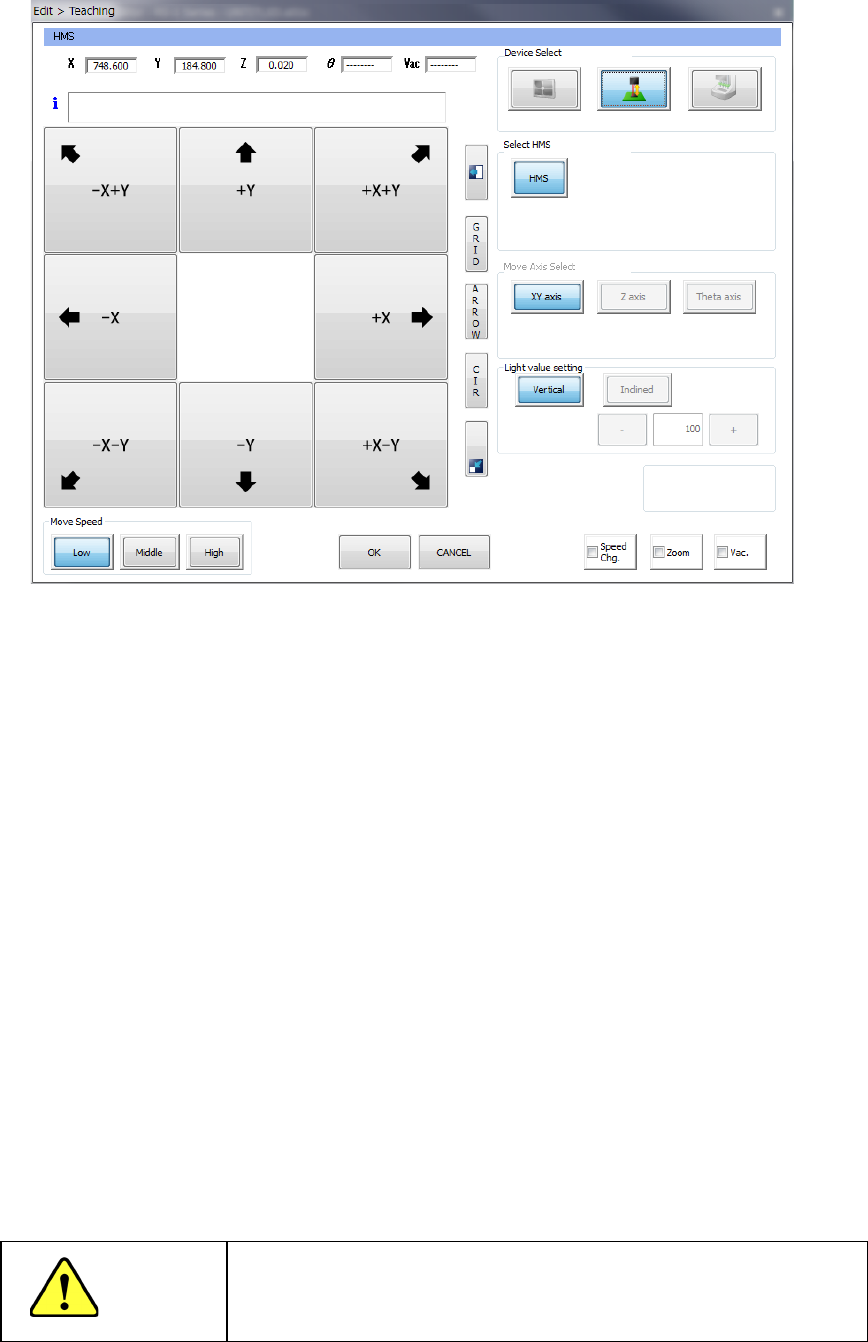
(2) Teaching with an HMS
1) Device Select
These buttons switch a device used to perform teaching to another one.
2) Select HMS
These buttons specify an HMS to be used to perform teaching.
3) Teaching Point
Any of these buttons cannot be used with the HMS to perform teaching.
4) Light value setting
Any of these buttons cannot be used with the HMS to perform teaching.
5) Move Speed
Operate these buttons in the same manner as teaching with a camera.
6) Feed pitch
Set a value when you want to change the feed pitch of the electric feeder.
When you select an HMS device, the selected HMS lights up. When you press one of eight
arrow keys on the left side of the screen, the XY axes move, and the axes continue to move
while you are touching the button. The current coordinates X, Y and Z (values measured
with the HMS) to which the HMS has moved are displayed in the text boxes displayed on the
upper section of the screen.
CAUTION
To avoid a risk of injury, do not put your hands inside the machine
or move your face or head close the machine while the system is
teaching data.
Part 1 Basic Operation Chapter 4 Creating a Production Program
4-183
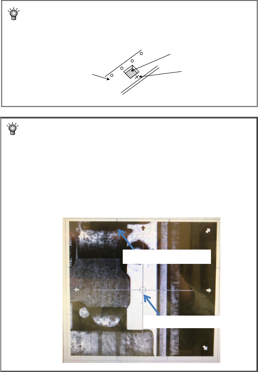
When you use the HMS to teach the height of a component, a laser beam is
reflected due to the surface condition (such as a gloss and roughness) of the top
side (to be measured) of a component, and the system may not be able to measure
the height of the component.
In such a case, move the laser beam onto the tape carrier as shown in the figure
below, and use that point alternately to teach the Z-axis.
When you use the HMS to perform a teaching operation of a feeder RF04AS, a
tape, which is a surface to be measured, transmits the laser beam if the tape is
transparent or translucent. Therefore, the system cannot obtain any correct
measured value, and then the component pick-
up ratio may be made worse in
some cases. In such a case, move the laser beam to the tape travelling surface as
shown in the figure below, and then perform a teaching operation of the Z-axis at
this point. In addition, measure the thickness of the carrier tape (except the cover
tape), and then enter a value to the menu item for the picking stroke displayed on
the screen for the component pick-
up conditions invoked from the “Component”
data screen as described below.
(Example: when the tape thickness is 0.3 mm, 0.05 - 0.3 = - 0.25 mm)
Using this value as the default value, make fine adjustments of the picking stroke
when necessary.
Tape carrier
Component
Measurement point
Component pick-up position
Tape travelling surface
Part 1 Basic Operation Chapter 4 Creating a Production Program
4-184
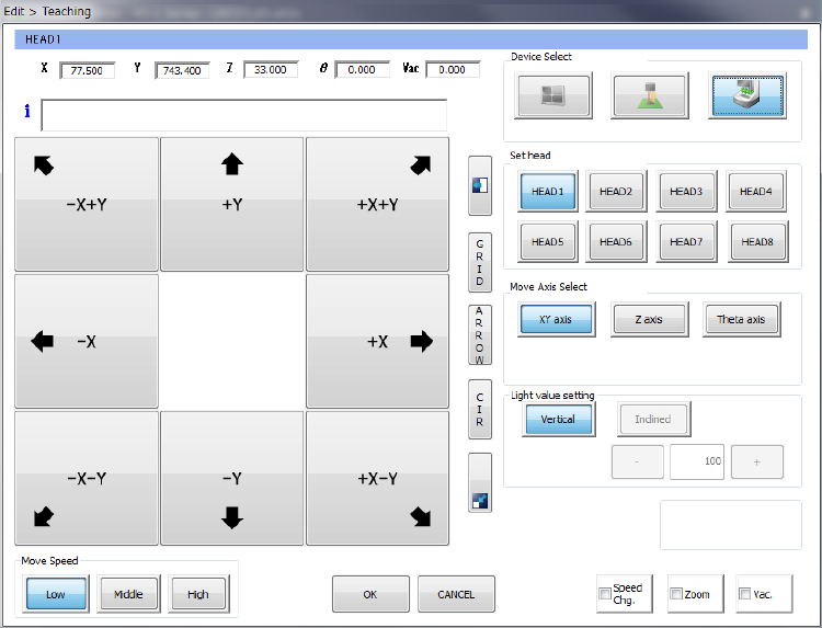
(3) Teaching with a head device
The head device teaches the XY-axes, the Z-axis and the θ-axis respectively.
1) Device Select
These buttons switch a device to be used to perform teaching to another one.
2) Set Head
Specify a head nozzle to be used to perform teaching.
3) Move Axis Select
These buttons change the axis to be moved.
4) Light value setting
You cannot set this item by teaching with a head device.
5) Feed pitch
Set a value when you want to change the feed pitch of the electric feeder.