RS-1_instruction manual.pdf - 第424页
Part 1 B asic O peration Chapter 4 Cr eating a Produc tion Progra m 4- 89 e) Bend level Enter the leve l for detecting a bent lead: whether a lead is bent in the hor izontal direction. A value you should enter here indic…
Part 1 Basic Operation Chapter 4 Creating a Production Program
4-88
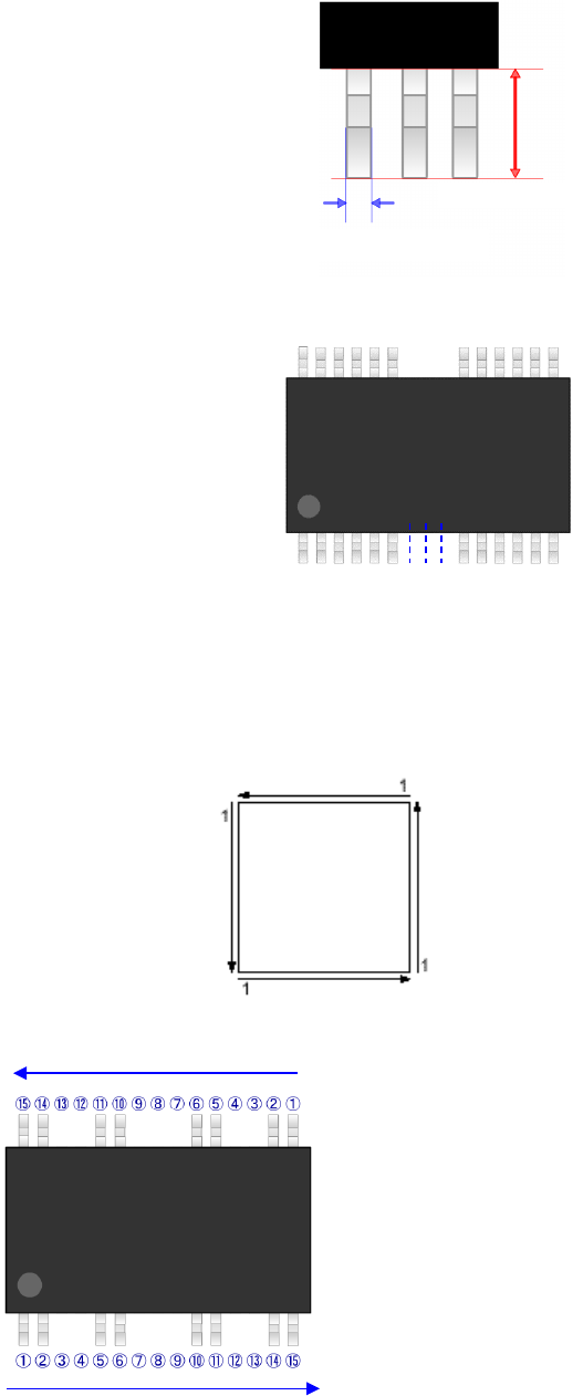
b) Width
Enter the width of a lead.
c) Number of leads (bottom, right, top and left)
Enter the number of leads of each side.
d) Start/lack (bottom, right, top and left)
When any lack of lead is found on each side, enter the lack information.
The lack information can be set independently for each side.
Up to 3 positions can be set for one side.
Leads on each side should be numbered in the direction shown in the diagram below.
Example)
①
⑥
⑩
⑮
Number of leads 15 (including the
number of the lower side missing leads)
Start 1 3 (From the 3rd lead)
Lack 1 2 (2 missing leads)
Start 2 7 (From the 7th lead)
Lack 2 3 (3 missing leads)
Start 3 12 (From the 12th lead)
Lack 3 2 (2 missing leads)
Top
Left
Bottom
Right
Lead length
Width of a lead
Part 1 Basic Operation Chapter 4 Creating a Production Program
4-89
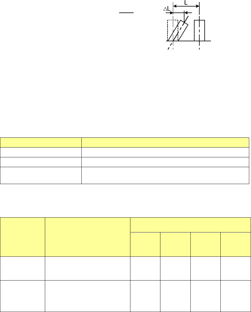
e) Bend level
Enter the level for detecting a bent lead: whether a lead is bent in the horizontal direction.
A value you should enter here indicates the ratio: how much a lead is bent against the lead
pitch. Normally, enter a value from 20 % to 30 %.
The smaller this value is, the more strictly the system inspects a component.
③ Lead direction
When the component type is a unidirectional lead connector, set whether the surface with
lead should be up or down.
④ Lead recognition types
For connector components, usually, all leads can be recognized.
However, when only the leads at both ends can be recognized or when there are luminous
materials other than leads at both ends, only the leads at both ends can be recognized or
the luminous materials are supposed to be leads and can be recognized excluding the leads
at both ends.
Item Contents
All leads All the leads are recognized.
Leads at both ends Specify the lead range to be recognized from both ends of leads.
Others than leads at both
ends
Specify the lead non-recognition range from both ends of leads
When you specify "Leads at both ends" or "Others than leads at both ends", enter the
number of leads in the upper left, upper right, lower left, and lower right corners to specify
the recognition range.
Component
type
Recognition pattern
Lead-number input range
Upper
left
corner
Upper
right
corner
Lower
left
corner
Lower
right
corner
Unidirectional
connector
All leads
Leads at both ends
Others than leads at both ends
****
1-3
0-3
****
1-3
0-3
****
****
****
****
****
****
Bidirectional
connector and
Z-lead
connector
All leads
Leads at both ends
Others than leads at both ends
****
1-3
0-3
****
1-3
0-3
****
1-3
0-3
****
1-3
0-3
* When the number of leads is 2 or less, the recognition accuracy may be lowered.
ΔL
L
Level for detecting a bent lead
Part 1 Basic Operation Chapter 4 Creating a Production Program
4-90
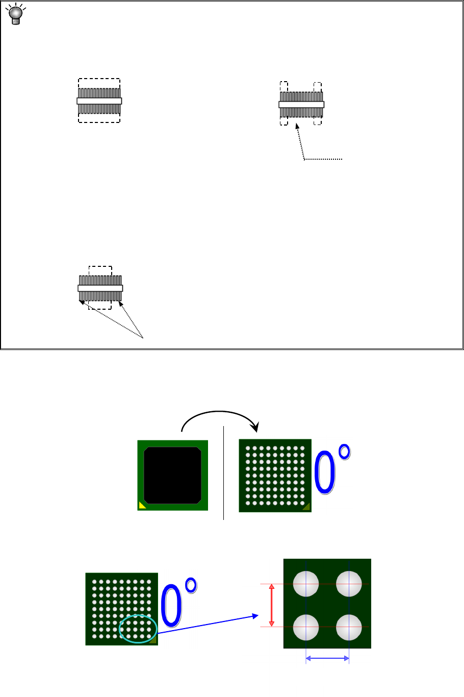
<Meaning and image of the lead recognition pattern
•
All: The system is supposed to
recognize all leads of a component.
•
Only the both ends lead: The system is
supposed to recognize only leads located at
both ends of a component.
• Both ends lead exclusion: The system is supposed to recognize only leads excluding ones
located at both ends of a component.
* Enter the number of leads to be recognized. (Not including the number of leads that
should be excluded.)
2) Component type: Ball component
* For vision data of the ball component, create data by component bottom view.
Set each ball information seen in the bottom view.
① Ball pitch
Enter the distance (X, Y) between balls.
The system will not
recognize the leads
located on the inside.
The system will not recognize the leads
located at both ends.
Recognized
Recognized
Recognized
Recognized
Recognized
Recognized
Recognized
Recognized
Top view
Bottom view
X
Y
Pitch between balls