RS-1_instruction manual.pdf - 第964页
Part 2 D etaile d Descript ion of E ach Functi on Chapter 12 Handling th e Optional Device s 12 - 80 12.13.2.2 Replacing a nozzle attachment When you re place a nozzle att achment of a low loa d contr ol nozzle with anot…
Part 2 Detailed Description of Each Function Chapter 12 Handling the Optional Devices
12-79
12.13 Load Control
12.13.1 Overview of the function
12.13.1.1 Low load control
When placing fragile components, the damage to the components are reduced.
After the machine finishes recognizing nozzles with the [ATC nozzle setup] command on the
“Machine Setup” screen, it automatically checks load (analyzes a failure such as a sliding failure).
By controlling load on the load cell, the machine can also check impact load against a component
when it controls load.
12.13.2 Load control nozzle
12.13.2.1 Low load control nozzle
Low load from 98 g to 507 g is controlled with the push-in amount, and the dedicated low load
control nozzle is used for this control operation.
A nozzle tip is attached on the end of the low load control nozzle, and you can replace it with a new
one at regular intervals.
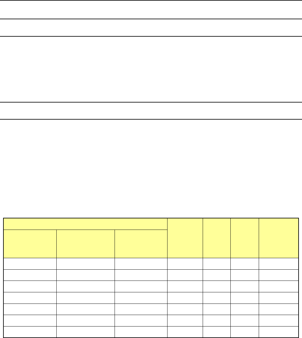
Three types of nozzles: 76*1, 76*2 and 76*3 are provided for various load areas, and the machine
can support various types of components if you replace a nozzle attachment.
For a nozzle (#7601 or higher) whose load is to be controlled, you can enter the push-in amount
(“Stroke”) by the load (g) on the “Component” data of a production program, and the machine can
control low load with calculating the push-in amount based on the measurement data obtained
when the machine runs a load check.
Nozzle number
Nozzle
attachment
Inside
diameter
(Ba)
Outside
diameter
(Bb)
Applicable
component
width
(mm)
76*1 type
(Load area:
98 to 135 g)
76*2 type
(Load area:
146 to 270 g)
76*3 type
(Load area:
245 to 507 g)
7611
-
-
701
φ
0.4
φ
0.75
0.45 - 0.8
7621
7622
-
703
φ
0.6
φ
1.25
0.75 - 1.5
7631 7632 - 705 φ1.15 φ1.75 1.3 - 2.7
7641
7642
-
707
φ
1.65
φ
2.25
2.5 - 3.5
7651
7652
7653
709
φ
2.2
φ
3.0
3.0 - 4.0
7661 7662 7663 711 φ3.2 φ4.0 4.0 - 6.0
7671 7672 7673 713 φ4.2 φ5.0 5.0 - 8.0
* The inside diameter and the outside diameter above indicate the dimensions of a nozzle
attachment.
Part 2 Detailed Description of Each Function Chapter 12 Handling the Optional Devices
12-80
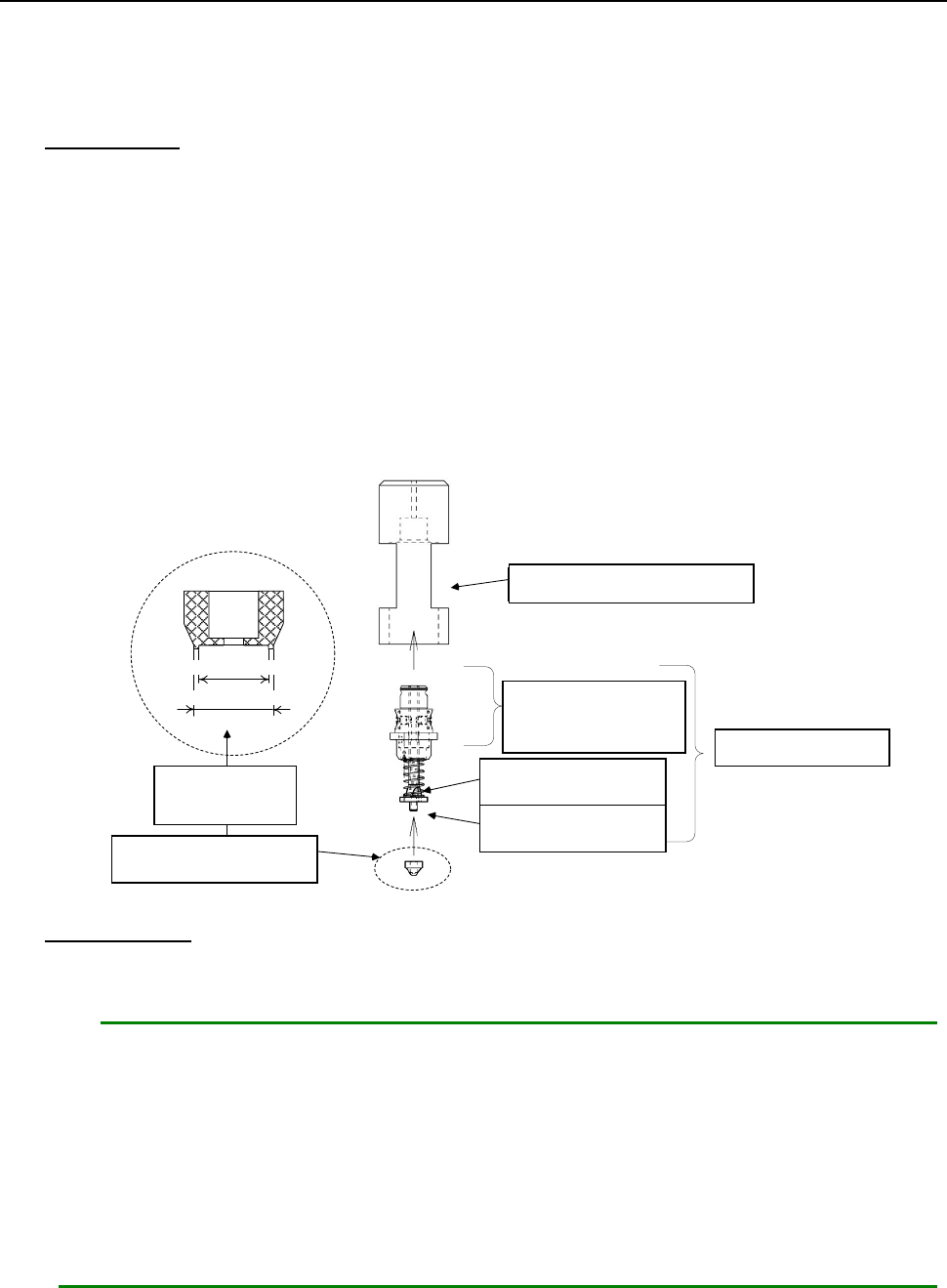
12.13.2.2 Replacing a nozzle attachment
When you replace a nozzle attachment of a low load control nozzle with another one, the nozzle can
support other types of components.
Follow the instructions below to replace a nozzle attachment with another one.
How to attach
1. Put the nozzle body (②) into the attachment push-in jig (①).
2. Insert the nozzle attachment (⑤) into the nozzle slider (④).
Pay attention so that any dust or stain cannot be adhered between the nozzle slider and the
nozzle attachment.
3. Push the nozzle attachment against the clean and flat surface, and push it enough until any
space cannot be formed between the attachment push-in jig and the flat surface.
4. Remove the nozzle from the attachment push-in jig, and then check to see if there is no
clearance between the seating face of the nozzle attachment and the nozzle slider mounting
surface, and any foreign substance is not caught between them.
① アタッチメント押込治具
③ ノズル スプリング
④ ノズル スライダ
A部: この部分は外面黒色
② ノズル ボディ
⑤ ノズル アタッチメント
内径
外径
拡大
How to remove
1. Hook your nail over the nozzle attachment, and pull it along the entire circumference of the
attachment little by little to remove it.
Notes:
1. If the seating face of the nozzle slider (the surface with which the nozzle attachment
is in contact) is scratched or damaged, it may cause an image recognition error.
When attaching/detaching the nozzle attachment, be careful not to scratch or
damage the surface.
2. If you repeat attaching/detaching a nozzle attachment, the insert hole is worn out.
It is recommended that you repeat attaching/detaching it up to ten times.
* A nozzle and a nozzle attachment are consumable goods. If any of them is defaced
or worn out, replace it with a new one.
①
Attachment push-in jig
②Nozzle body
③
Nozzle spring
④
Nozzle slider
⑤
Nozzle attachment
Enlarged
figure
Section “A”: The
external surface of
this part is black.
Outside diameter
Inside diameter
Part 2 Detailed Description of Each Function Chapter 12 Handling the Optional Devices
12-81
12.13.3 Setup
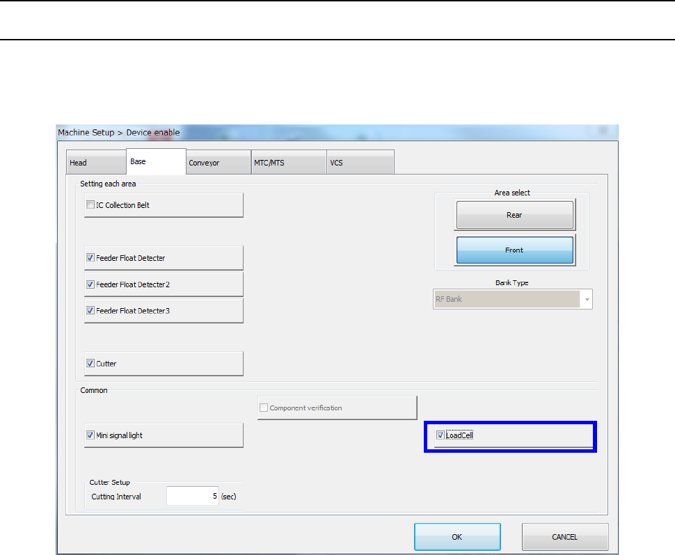
12.13.3.1 Setting on the “Device enable” screen (Enabling/disabling a load cell)
Select the [Setting group] command on the “Machine Setup” screen, and then the [Device enable]
command. Next, select the “Base” tab, and then check to see if a checkmark is placed in the “Load
Cell” check box.