RS-1_instruction manual.pdf - 第716页
Part 2 D etaile d Descript ion of E ach Functi on Chapter 8 Machine Set up 8-8 Base W hen yo u sel ec t “ Base ”, the foll owing scre en appears. When you clic k each ta b, you can spec ify each of “ Head , ” “ Base, ” “…
Part 2 Detailed Description of Each Function Chapter 8 Machine Setup
8-7
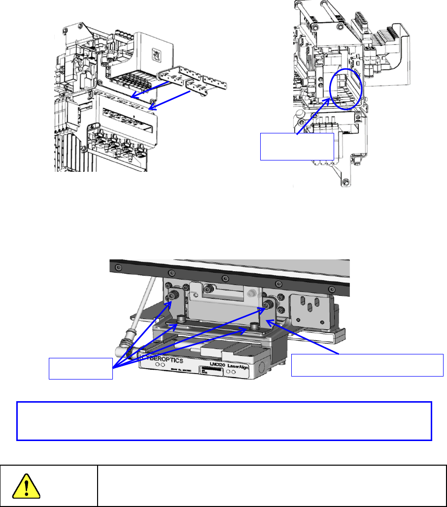
2. Install the ZM STOPPER ① with the screw ③ and press it against the Z axis pulley
and
f
asten with the screw ③.
【UNTIL HEAD Rev. A, Shared After.】
1. When not using the ZA axis, attach ZA_FIXED_BRACKET (40182877) and fix the ZA
axis.
Danger
To prevent an accident due to a sudden start, turn off the power
supply before starting operations.
- Make sure that the Z-axis is provided at the top position and install the fixture.
- Make sure that the Z-axis is fixed with the fixture.
ZA_FIXED_BRACKET (40182877)
Screw M3
Set screw③
Part 2 Detailed Description of Each Function Chapter 8 Machine Setup
8-8
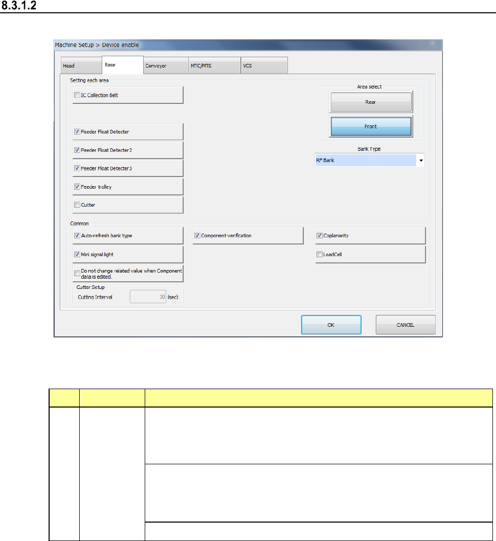
Base
When you select “Base”, the following screen appears.
When you click each tab, you can specify each of “Head,” “Base,” “Conveyor,” “MTS” and “VCS.”
(1) Setting items
No. Item Description
1 Base
Specify whether to use a device or not.
If you set one device not to be used on this tab, when it malfunctions the
system can continue picking up and placing components without
changing data of a production program.
Displays the bank type of each bank.
Note that when the machine is designed to be equipped with fixed banks
only, the front bank is fixed to the RF bank only, while the rear bank is
fixed to the RF/EF bank only.
Specify the repetition interval of cutter setting.
If a production program requires any function displayed on the screen above to finish placing
a component on a board completely, whether the system can place a component actually is
shown in Table.

Part 2 Detailed Description of Each Function Chapter 8 Machine Setup
8-9
No. Unit Production operation
1
IC Collection Belt
(Front/Rear)
This function is just deleted, and placement is executed.
2
Feeder Float Detector
(Front/Rear)
This function is just deleted, and placement is executed.
3
Feeder trolley
(Front/Rear)
This function is just deleted, and placement is executed.
4
Cutter
(Front/Rear)
This function is just deleted, and placement is executed.
5
Area select
(Front/Rear)
This function is just deleted, and placement is executed.
6 Auto-refresh bank type
This function is just deleted, and placement is executed.
7 Mini signal light This function is just deleted, and placement is executed.
8 Component verification
No verify operation is performed even if Component
verification is specified.
9 Coplanarity
The machine places a component on a board without
running a coplanarity check even though the component
coplanarity is specified.
10 Load Cell
The load nozzle check is not run even though a load control
nozzle is used.
11
Do not change related
value when Component
data is edited.
If you set this function to ON, the number of items whose
default values have to be set again due to change of one
data item is minimized when you edit the Component data
already set.
(2) How to set
1) Specify a device to be used by check button.
When a check mark is attached, this means a “Use” setting. If no check mark is
attached, this means a “No use” setting.
2) It is impossible to select a unit that is not set as an option (unit indicated in light
characters).
3) Enter a value in the “Cutter Interval” field from a keyboard directly. Note that you
cannot enter any value in this field if the cutter is set to be unused.