RS-1_instruction manual.pdf - 第940页
Part 2 D etaile d Descript ion of E ach Functi on Chapter 12 Handling th e Optional Device s 12 - 56 12.11.3 Machi ne Set up 12.11.3.1 Enabling/ Disabling the Offset P lacement After Solder Screen - Printing option Selec…
Part 2 Detailed Description of Each Function Chapter 12 Handling the Optional Devices
12-55
12.11.2.2 What to check
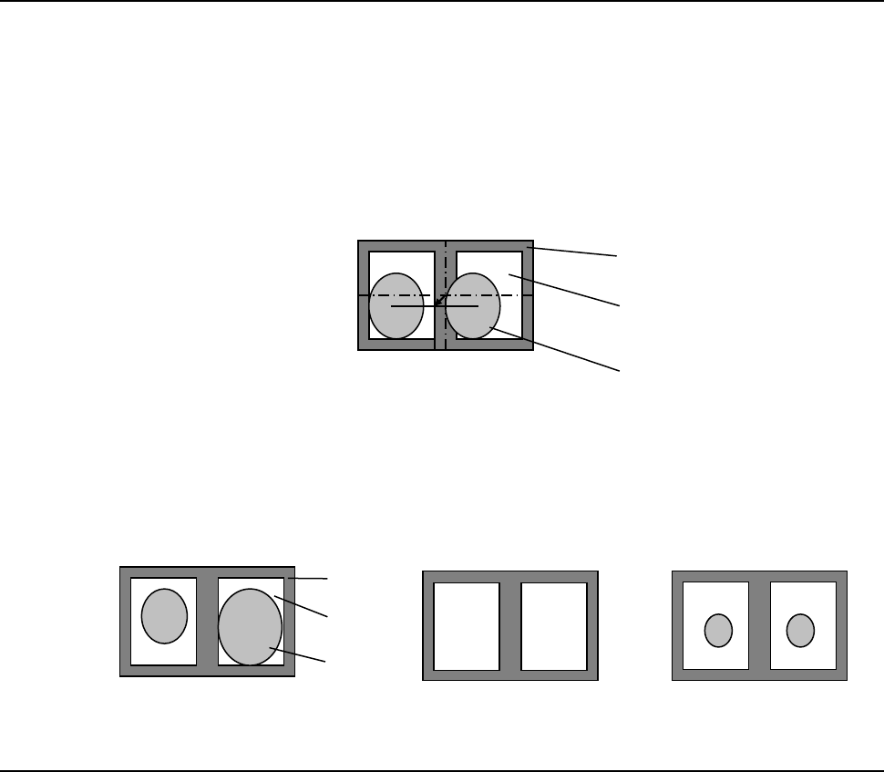
This option detects the gravity of the screen-printed solders (at two positions) and corrects the
difference from the programmed component placement coordinates to place a component.
The option checks the “position error” of the screen-printed solder and “its condition.”
① Checking the position error
If screen-printed solder misalignment detected when the system recognizes solder exceeds
the threshold value set in advance, the system detects an error. The system also calculates
the default solder detection area by referring to the misalignment check value.
② Checking the condition
If the area ratio of a pair of solder printed areas exceeds the threshold set in advance when
the system recognizes solder, the system detects an error. Set the threshold value in
percent as the allowable difference of the areas based on the larger solder area. If there is
no solder printed or if the outer size of the solder is different from the taught size by
approximately 30% or more, a recognition error occurs.
12.11.2.3 Others
− A BOC mark should be always used to use this Offset Placement After Solder Screen-Printing
option.
− To set a solder recognition mark with an external device, it is recommended to name the mark
ID such as a [S001] so that it can be distinguished from a normal fiducial mark easily. You
have to check a solder mark to be registered in advance.
− If any adhesive is applied to a mark, you cannot use this Offset Placement After Solder
Screen-Printing option.
PWB
Pad
Solder
PWB
Pad
Solder
Part 2 Detailed Description of Each Function Chapter 12 Handling the Optional Devices
12-56
12.11.3 Machine Setup
12.11.3.1 Enabling/Disabling the Offset Placement After Solder Screen-Printing option
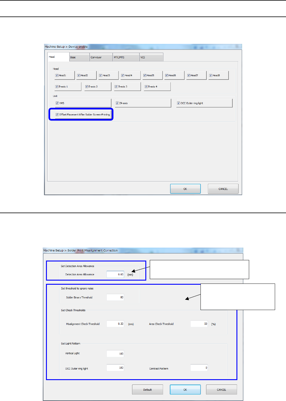
Select [Setting] – [Machine Setup] from the menu to open the “Machine Setup” screen. Then,
select the “Device enable” tab, and then the “Head” tab to check off or uncheck the “Offset
Placement After Solder Screen-Printing” check box.
12.11.3.2 Setting Solder Print Recognition Mounting Position Correction Parameters
When you select [Function setting] – [Solder print misalignment correction] on the machine setup
screen, the following [Solder print misalignment correction” screen is displayed.
With this screen, the margin for the solder detection range can be set and parameters for teaching
can be used to modify initial values.
Margin setting to the solder
detection area
Change of the initial
value of the parameter
for teaching
Part 2 Detailed Description of Each Function Chapter 12 Handling the Optional Devices
12-57
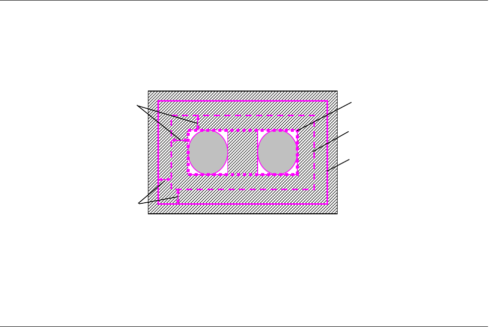
12.11.3.2.1 Setting an offset of the detection area
Set an offset value of the solder detection area with the “Set Margins for Detection Area” column
displayed on the “Solder Print Misalignment Correction” screen invoked from the “Function setting”
command of the “Setup” utility. Enter the desired value when you want to enlarge the detection
area based on the range calculated with the misalignment check value. The system recognizes
solder within the range obtained by adding the offset value to the misalignment check value.
* Even though you enter an offset value, the detection area is expanded only, and the judgment
value for the misalignment check does not change. However, when the detection area is
expanded, the system may by mistake detect solder not to be recognized, and recognition may
be unstable.
12.11.3.2.2 Setting the Initial Values for Teaching Solder
You can set the initial values of the parameters to be set for solder teaching.
You can set the following initial values for each mounter: [Solder Binary Threshold], [Misalignment
Check Threshold], [Area Check Threshold], [Vertical Light], [OuterRing] and [Contrast Pattern],
which are to be set for solder teaching.
When you select the <Default> button, all of the setting values are restored to the initial values set
at the factory.
Detection area margins
Misalignment check values
Shape of solder
Default detection area
Detection area