RS-1_instruction manual.pdf - 第240页
Part 1 B asic O peration Chapter 2 Pr oduction 2- 129 Clearing c orrection of a component pick - up position Overview Select the m enu co mmand [ Auto - Corr ect pick pos ition Clear] from the “ Suppor t” menu invo ked f…
Part 1 Basic Operation Chapter 2 Production
2-128
In this case, the automatically calculated laser position is used as the “Present position” at
start of the “Range of laser position measurement.” Therefore, you cannot specify the
desired laser position.
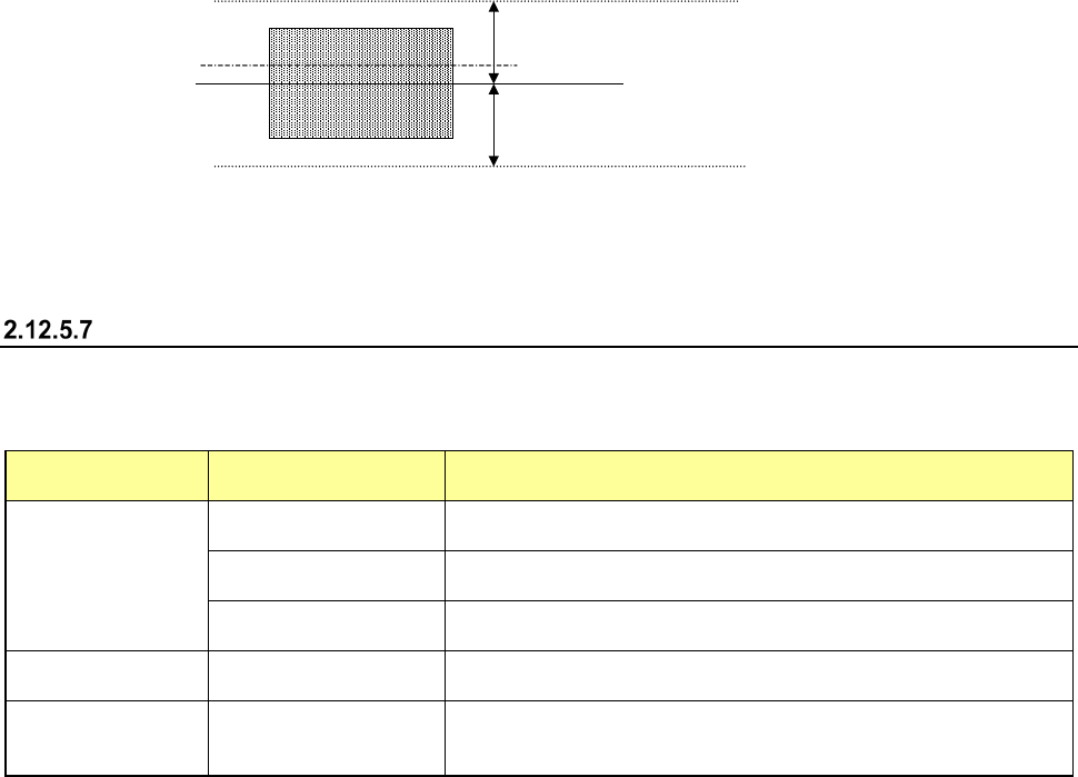
(3) Range of laser position measurement
Specify the range of measurement. (See the later section for the positional relation between
the range of measurement to be repeated and the component and laser heights.)
1) Move direction
a) Present position
The system repeats measuring the laser position from the position displayed in the
“Laser Height” of “Laser position measurement value” within the specified range.
When the system successfully centers a component with laser, it finishes measuring the
laser position.
b) Pick face of comp. → face under comp.
c) face under comp. → Pick face of comp.
The system measures the component height independently from the value displayed in
the “Result of Inspection.”
The system can measure the component height either from the pick-up surface or the
bottom.
2) Direction of movement
(a) Alternation
(b) Up
(c) Down
3) Stepping/Range (The top and bottom)
Specify a step by which the laser should move during measurement and the laser moving
range.
Moving rang
Movement step
Current laser position
Moving rang
Side of a component
(4) Result of inspection
When the system centers a component with laser, it displays the laser status value here in the
same manner as on the screen “Continuous laser position inspection is being executed” (Laser
position inspection). The same screen as the “Laser position inspection” screen appears.
“Range of laser position measurement”
Depending on the measurement operation on the screen and/or your selection of the measurement
direction (selection of “Direction of movement”), the range within which the system is to repeat
measuring to check the laser position varies.
“Move direction”
selection
“Direction of
movement” selection
Description
Present position
Alternation
The system continues checking a component from the present
position toward the up, then down direction alternately.
Up
The system checks a component from the present position toward
the up direction continuously.
Down
The system checks a component from the present position toward
the down direction continuously.
Pick face of comp.
→
face under comp.
−
The system checks a component from the component height toward
the face of the component to be picked up, then the bottom side.
face under comp. →
Pick face of comp.
−
The system checks a component from the component height toward
the bottom side of the component, then the face of the component to
be picked up.

Part 1 Basic Operation Chapter 2 Production
2-129
Clearing correction of a component pick-up position
Overview
Select the menu command [Auto-Correct pick position Clear] from the “Support” menu invoked from
the “Production” menu.
This function clears data for correcting a component pick-up position.
You can select this function when the menu item “The feed amount is adjusted by teaching.” is
selected on the “Operation option” screen.
Part 1 Basic Operation Chapter 2 Production
2-130
2.13 Tool
Operation option
When you select the [Tool] command from the “Product” menu, and then the [Operation option]
command, the “Operation option” screen appears.
See Chapter 7 “Operation Option” for details.
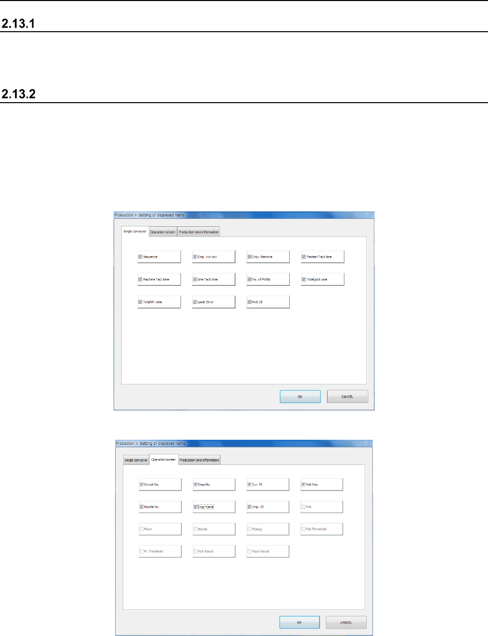
Setting of the displayed items
When you select the [Tool] command from the “Product” menu, and then the [View Log File]
command, the error log display screen appears.
This screen allows you to display or hide an item to be displayed during PWB production.
The items displayed on the “Production condition” screen when the machine uses the single-lane
conveyor to produce PWBs are different from those when it uses the dual-lane conveyor to produce
PWBs.
The “Single conveyor” tab allows you to display or hide the items on the “Production condition”
screen when the machine uses the single-lane conveyor to produce PWBs.
The “Operation screen” tab allows you to display/hide menu items on the “Production status
(Operation condition)” screen.