RS-1_instruction manual.pdf - 第238页
Part 1 B asic O peration Chapter 2 Pr oduction 2- 127 Interrupting the continuous laser position inspection T o terminate the conti nuous laser position ins pection forcib ly , press the <ST OP> sw itch. T he follo…
Part 1 Basic Operation Chapter 2 Production
2-126
(1) Progress situation
This progress bar indicates how far the check has progressed.
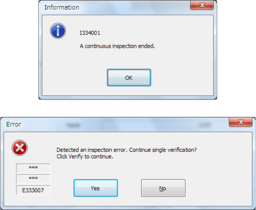
When the system finishes continuous inspection, it outputs the following message, and then
returns to the previous screen (“Continuous laser position inspection” screen).
If an error occurs during continuous inspection, the following message is output.
To inspect the next component, press the <Yes> button. The system restarts continuous
inspection.
To inspect a component that caused an error separately, press the <Yes> button.
You can inspect only a component that caused the inspection error.
(2) Component (to be inspected)
The component number (“No.”), the component type (“Type”), the packaging style
(“Package”), the nozzle number (“Nozzle No.”), the component name (“Name”), the bank
(“Bank”), the attachment hole (“Slot No.”) and the lane (“Lane No.”) are displayed here.
(3) Pickup position
The coordinates of a component pick-up position are displayed here.
(4) Inspected value
The laser height and component height to be checked are shown here.
• <Meas.> button
This button allows you to measure the laser position.
(See the next section for the laser position.)
(5) Result of inspection
After inspection, the result value appears in the “Result of inspection” column.
1) Status
OK : he centering operation is done successfully.
Number : the system failed to center a component (each number indicates a code
number of the laser status).
2) Width, Length
The size of a component that was centered successfully appears here.
3) Angle
The angle of the component obtained when it is centered appears here.
Part 1 Basic Operation Chapter 2 Production
2-127
Interrupting the continuous laser position inspection
To terminate the continuous laser position inspection forcibly, press the <STOP> switch. The
following message is output on the screen.
To terminate the inspection, select the <Yes> button.
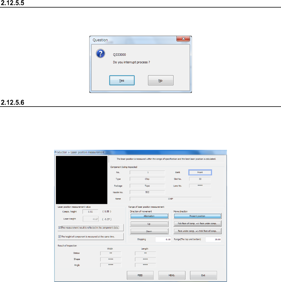
Laser position measurement
When you press the <Meas.> button on the screen for single laser position check, the following
“Laser position measurement” screen appears.
The laser position is repeatedly measured according to the conditions and in the direction that are
shown below, and the system sets the laser position that centered a component successfully as the
optimal laser position.
(1) Component being inspected
Data on the component being inspected appears here.
(2) Laser position measurement value
The data required to measure the laser height is shown here.
1) Compo. Height
The component height is displayed here.
2) Laser Height
You can change the laser height (position) as you like.
The value you set here is to be used as the “Present position” at start of the “Range of laser
position measurement.”
3) “The measurement result is reflected in the component data.
Put a check mark in this check box to apply the measured laser position to Component data
immediately.
4) “The height of component is measured at the same time.
When you put a check mark in this check box, the system measures the component height
before measuring the laser position. At the same time, the system calculates the laser
position automatically.
Part 1 Basic Operation Chapter 2 Production
2-128
In this case, the automatically calculated laser position is used as the “Present position” at
start of the “Range of laser position measurement.” Therefore, you cannot specify the
desired laser position.
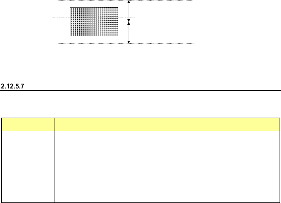
(3) Range of laser position measurement
Specify the range of measurement. (See the later section for the positional relation between
the range of measurement to be repeated and the component and laser heights.)
1) Move direction
a) Present position
The system repeats measuring the laser position from the position displayed in the
“Laser Height” of “Laser position measurement value” within the specified range.
When the system successfully centers a component with laser, it finishes measuring the
laser position.
b) Pick face of comp. → face under comp.
c) face under comp. → Pick face of comp.
The system measures the component height independently from the value displayed in
the “Result of Inspection.”
The system can measure the component height either from the pick-up surface or the
bottom.
2) Direction of movement
(a) Alternation
(b) Up
(c) Down
3) Stepping/Range (The top and bottom)
Specify a step by which the laser should move during measurement and the laser moving
range.
Moving rang
Movement step
Current laser position
Moving rang
Side of a component
(4) Result of inspection
When the system centers a component with laser, it displays the laser status value here in the
same manner as on the screen “Continuous laser position inspection is being executed” (Laser
position inspection). The same screen as the “Laser position inspection” screen appears.
“Range of laser position measurement”
Depending on the measurement operation on the screen and/or your selection of the measurement
direction (selection of “Direction of movement”), the range within which the system is to repeat
measuring to check the laser position varies.
“Move direction”
selection
“Direction of
movement” selection
Description
Present position
Alternation
The system continues checking a component from the present
position toward the up, then down direction alternately.
Up
The system checks a component from the present position toward
the up direction continuously.
Down
The system checks a component from the present position toward
the down direction continuously.
Pick face of comp.
→
face under comp.
−
The system checks a component from the component height toward
the face of the component to be picked up, then the bottom side.
face under comp. →
Pick face of comp.
−
The system checks a component from the component height toward
the bottom side of the component, then the face of the component to
be picked up.