RS-1_instruction manual.pdf - 第554页
Part 1 B asic O peration Chapter 4 Cr eating a Produc tion Progra m 4- 219 2) Au to - teachi ng a) Run Auto - t eaching The system automat i cally t eaches a comp onent pick - up posit ion. b) Check for Parallel Pi ck Ra…
Part 1 Basic Operation Chapter 4 Creating a Production Program
4-218
4.5.6.5 Pick position/Pick height
These commands use the camera to track the component pick-up position.
You can see the component placement position displayed on the monitor, so you can use the HOD
to teach the placement position if the entered coordinates are not appropriate.
When you use the HMS, the system can track the component pick-up height also. In this case,
the system displays the values detected with the HMS on the screen sequentially.
If the tracked height is quite different from the specified one, teach the height as well as the
coordinates.
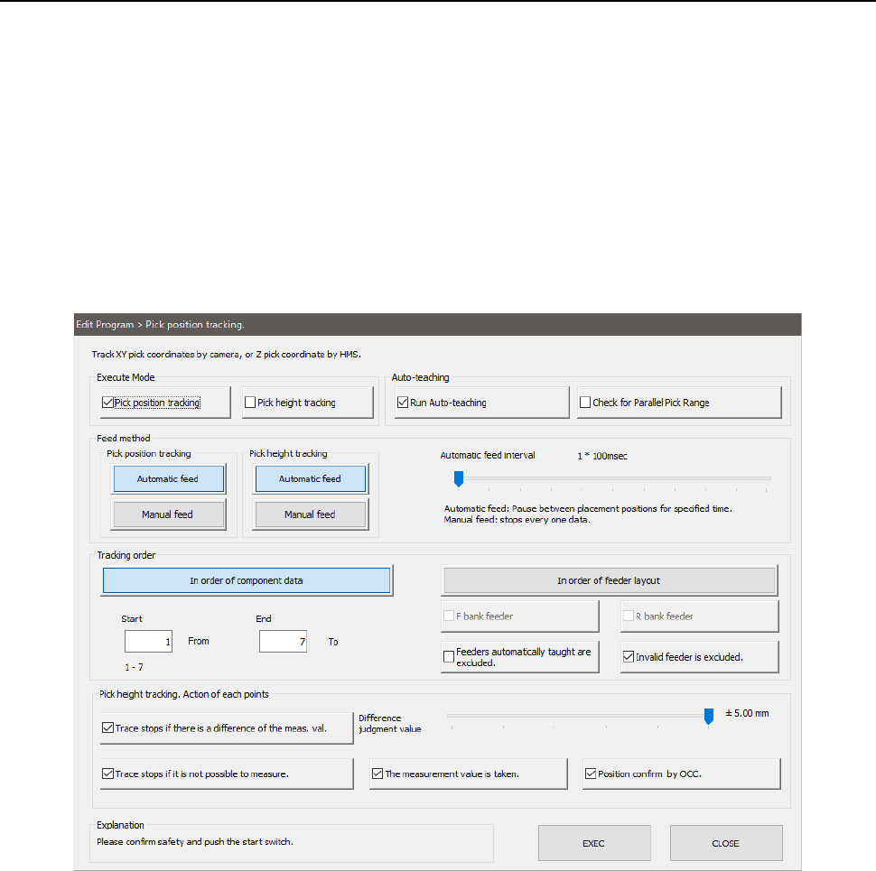
(1) Setting the tracking conditions
When you select the [Machine operation] command from the Program Editor menu, and
then the [Pick position] command, the following screen appears.
When you select the [Machine operation] command from the menu, and then the [Pick
height] command, the screen shown above appears on which the “Pick height tracking”
check box is checked off.
1) Execute Mode
a) Pick position tracking
The system tracks a component pick-up position with a camera.
b) Pick height tracking
The system tracks a component pick-up height.
* When both check boxes are checked off, the system tracks the pick-up height after
tracking the pick-up position with the camera.
Part 1 Basic Operation Chapter 4 Creating a Production Program
4-219
2) Auto-teaching
a) Run Auto-teaching
The system automatically teaches a component pick-up position.
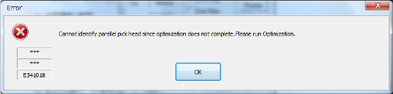
b) Check for Parallel Pick Range
The system checks whether two or more components can be picked up simultaneously.
You have to execute the Optimization utility in advance. If you do not execute the
Optimization utility yet before pressing this button, the error message appears on the
screen that asks you to execute the Optimization utility.
3) Feed method
a) Automatic feed
Each pickup position is caught by camera or HMS at certain intervals. The camera stops for
the time of period specified with the “Automatic feed interval” slider bar described below,
then moves to the next position.
• Automatic feed interval:
Use this slider bar to adjust the stop time. You can set an interval from 0.1 second (100 ms)
to 20 seconds.
b) Manual feed
The operation is stopped at each pick position.
The operation is stopped at the current position until the user performs any operation.
When the <Prev> button is pressed on the pick position camera tracking screen, the
operation is returned to the previous pick-up position. When the <START> switch is
pressed, the operation goes to the next pick-up position.
4) Tracking order
a) In order of component data
Enter the tracking range from the starting point to the ending point by component data No.
By default, all components are to be tracked.
b) The order of feeder layout
Specify the position to be tracked in bank units.
c) Feeders automatically taught are excluded.
When you set this check box to ON, the camera tracks a component pick-up position on
feeders except for the feeders automatically taught, and then tracks the component pick-up
height.
d) Invalid feeder is excluded.
When you set this check box to ON, the camera tracks component pick-up from feeders that
are not set to be skipped with Placement data, Component data, and/or Pick data, and then
tracks the component pick-up height.
5) Action of each points ("Pick height tracking")
You can specify an action to be taken after moving to each tracking point.
a) Trace stops if there is a difference of the measurement value.
When a difference between the detected value measured by HMS and the pickup height
value set in the pick data exceeds the allowable range set in the “Difference judgment value”
field, a message is displayed and the operation is stopped.
Set the upper limit/lower limit range of (Difference judgment value)( +/-) by the slider bar.
b) Trace stops if it is not possible to measure.
If the HMS cannot measure the pick-up height (for example, because there is no component
at the measured pick-up position), the message appears on the screen to stop the tracking
Part 1 Basic Operation Chapter 4 Creating a Production Program
4-220
operation.
c) The measurement value is taken.
This choice allows you to save the value measured by the HMS into Pick data by asking
whether to save it at each position.
d) Position confirm by OCC.
The pick-up position is displayed with an image shot with the camera only for the period of
time set with the “Automatic feed interval.”
(2) Executing the bank mark alignment operation
If the bank mark recognition is set on the Setup menu, the system recognizes a bank mark to
improve the precision of the component pick-up position before the camera or HMS moves to each
feeder bank. The following dialog box appears on the screen. Press the <OK> button.
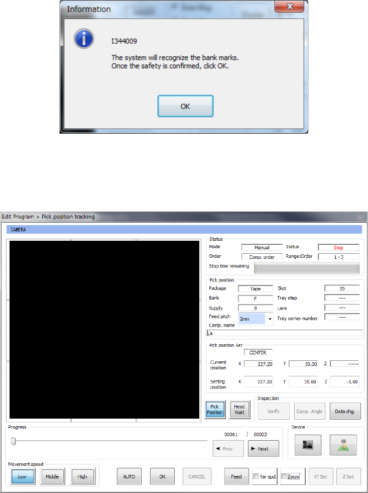
(3) While the camera is tracking a component pick-up position/the HMS is tracking component height
After the camera tracks the pick-up poison/height or when it is tracking each pick-up position, the
screen like the one shown below appears.