RS-1_instruction manual.pdf - 第744页
Part 2 D etaile d Descript ion of E ach Functi on Chapter 8 Machine Set up 8- 36 8.3.5 Function setting Pick error conditions When you se lect the [P ick error condit ions] command, the following scr een appears. Set the…
Part 2 Detailed Description of Each Function Chapter 8 Machine Setup
8-35
MTC shuttle pick position
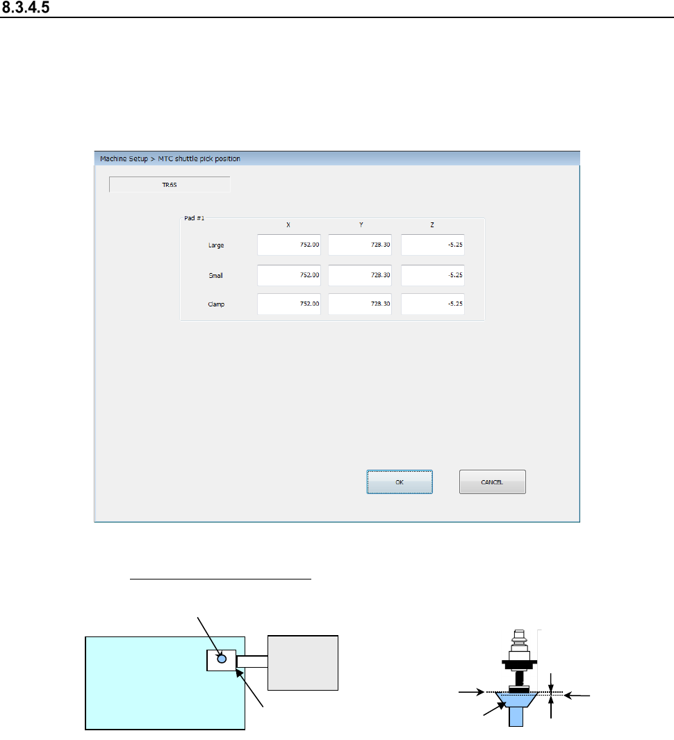
When you select the [MTC shuttle pick position] command, the following screen appears.
This screen allows you to specify the pick-up position (X, Y) of a component supplied from the
MTC.
Teach the position (X, Y) with the camera. Attach a 7508 nozzle on a head, and teach as the Z-
coordinate the height at which the bottom side of the nozzle comes in contact with the topside of
the pick-up pad of the shuttle on the MTC side.
(1) Setting item
① XY: Teach the center of the pad. ②
Z: Align the nozzle with the topside of the
pad, and then teach the position lower than
this side by 0.5 mm.
(2) How to set
Specify each coordinate with the teaching operation or using the keyboard.
When the input focus is in the “X” or “Y” field, the XY values are taught. When it is in the “Z”
field, the Z value is taught.
Teach the Z-coordinate while looking with eyes at the nozzle and the pad.
Note that the Z-coordinate of each of the “Large,” “Small” and “Clamp” fields is obtained and
displayed when one of them is taught.
MTC
<Top view>
Shuttle
Pad
0.5 mm
Z
Topside of
the pad
Part 2 Detailed Description of Each Function Chapter 8 Machine Setup
8-36
8.3.5 Function setting
Pick error conditions
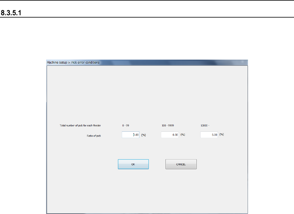
When you select the [Pick error conditions] command, the following screen appears.
Set the pick rate to the total number of picking operations for each feeder.
When “Display Pick Error” is checked off as an in-production display option, an error is displayed
if there is a feeder with a worse pick ratio than the setting before a start of production.
(1) How to set
1) Enter the total pick count for each feeder by the NUM button of the information area.
Part 2 Detailed Description of Each Function Chapter 8 Machine Setup
8-37
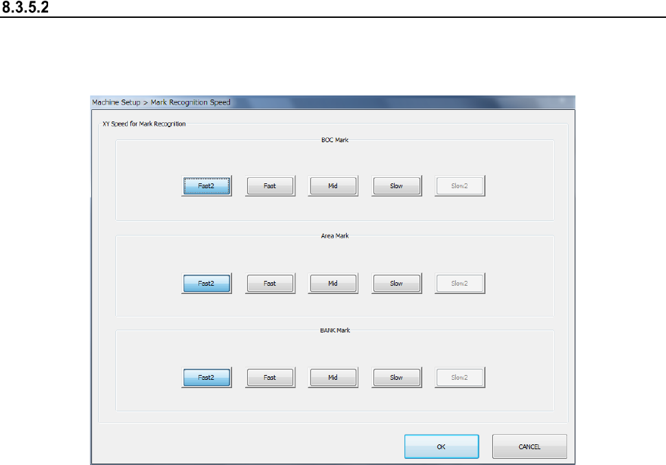
Mark recognition speed setting
When you select [Mark recognition speed setting], the following screen appears.
Perform this setting so as to change the axis speed in the mark recognition operation at
production. Set the XY speed for each recognition of BOC mark, area mark, and BANK mark.
(1) How to set
1) Set the speed by radio button for each mark. “Slow 2” is a particular ordering item.