RS-1_instruction manual.pdf - 第904页
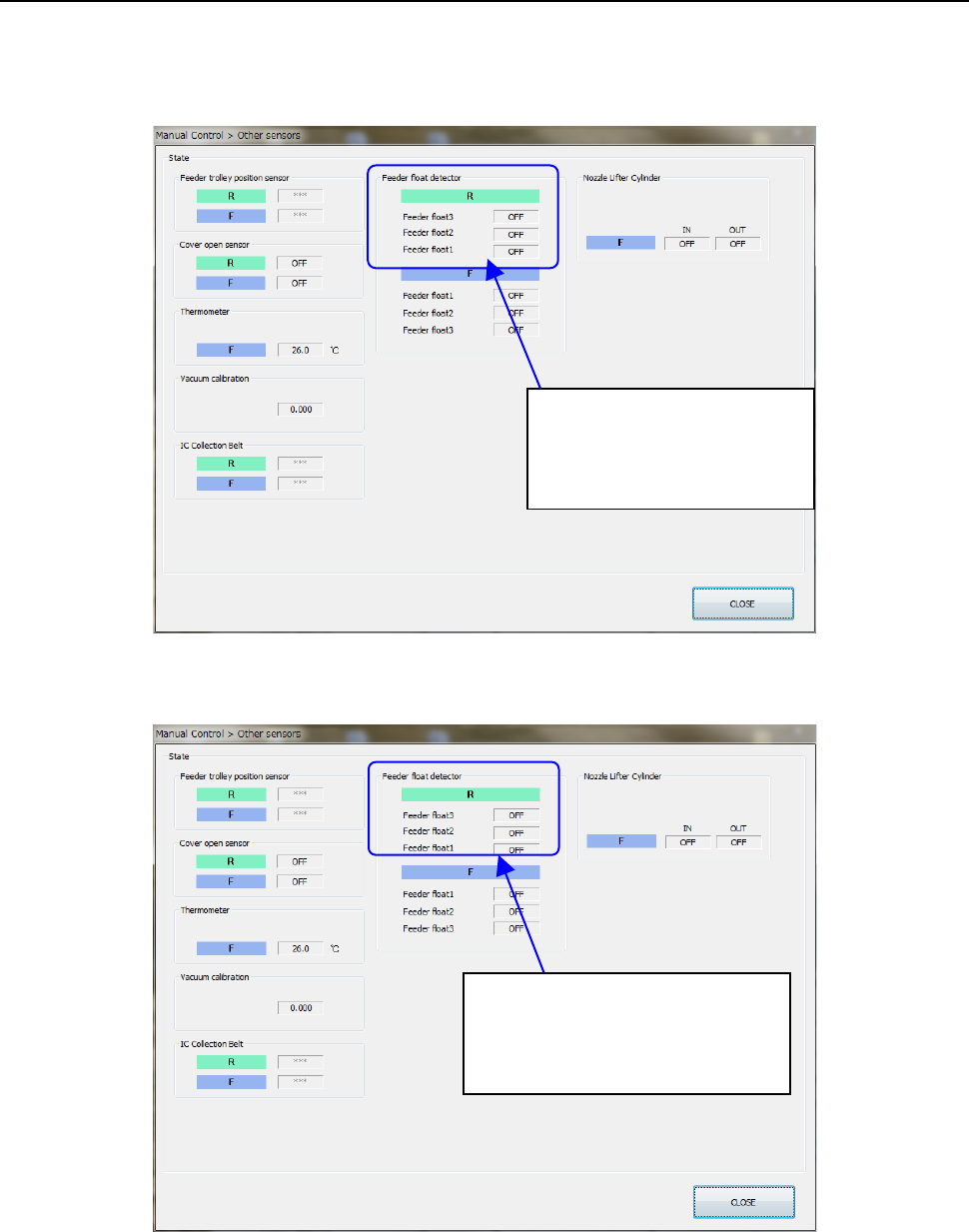
Part 2 D etaile d Descript ion of E ach Functi on Chapter 12 Handling th e Optional Device s 12 - 20 12.3.4 Checking the S ensor (When a TR8SR is selected) Select Manu al Control>Ot hers>Other sens ors and per form…
Part 2 Detailed Description of Each Function Chapter 12 Handling the Optional Devices
12-19
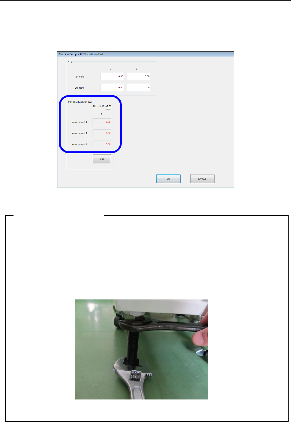
12.3.3.2 Checking the height
Set a tray base on the first stage of the MTS. After return-to-origin operation, display the “MTS
position offset” screen from the “Position setting” screen invoked from the “Machine Setup” screen,
and then press the <Meas.> button. The system pulls out the tray base, and automatically
measures the height. Check the screen shown below, and repeat this measurement operation and
adjustment of the height until a value in the range of – 10.00 mm to – 9.00 mm is displayed in each
of the “Measurement 1” field, the “Measurement 2” field and the “Measurement 3” field.
After the adjustment has been completed, tighten the adjuster nuts to secure the height.
• As the adjuster is turned one rotation, the height changes 2.5 mm.
• Since the adjuster screw has a play, pay special attention to the following points when
securing the adjuster with the nut.
① Adjust the Z-height to around -9.15 mm by taking the play into consideration.
② When tightening the fixing nut, put a spanner on the height adjustment nut and
hold it so that the adjuster does not turn.
• Turn four casters and four adjusters evenly to install them.
• After the setup has been completed, insert the RF08AS into the rear lane No. 14.
When there is no interference, this position becomes the correct position.
Tips on leveling work
Part 2 Detailed Description of Each Function Chapter 12 Handling the Optional Devices
12-20
12.3.4 Checking the Sensor (When a TR8SR is selected)
Select Manual Control>Others>Other sensors and perform the following work using the RF08AS to
check the operation status of the rear feeder float sensor.
• Open the feeder cover intentionally to check that the sensor turns ON when the feeder is
inserted into the bank.
• When pulling out the feeder from the bank with the feeder cover closed correctly, check that
the feeder can be pulled out with the sensor turned OFF.
If incorrect detection or non-detection occurs, readjust the height of the feeder float sensor on the
TR8SR side.
The feeder float detector is
• ON when detected.
• OFF when not detected.
The feeder float detector 2
・
3 is
• ON when detected.
• OFF when not detected.
Part 2 Detailed Description of Each Function Chapter 12 Handling the Optional Devices
12-21
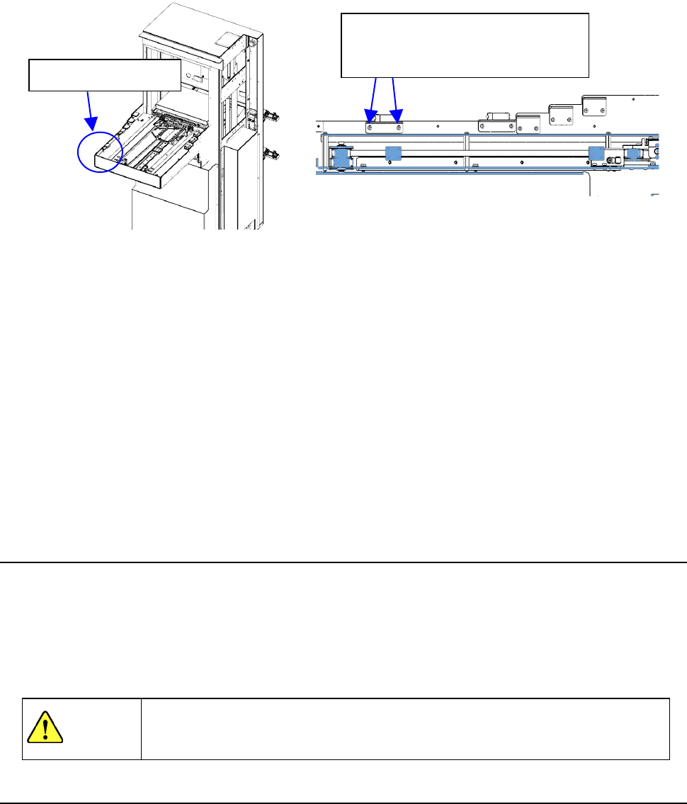
Work procedures
① In case of TR8SR, please open the feeder cover of RF08AS and insert it in rear lanes 1, 10,
20 lane.
② If the feeder cover you have opened is not detected, gradually lower the feeder float sensor
on the TR8SR side to a position where the opened cover is detected.
③ Insert 8 mm feeder, TR8SR to rear 1st, 10th, 20th and it has a play of the rail when you pull
out the feeder.
④ If incorrect detection occurs, gradually raise the feeder float sensor on the TR8SR side to a
position where no incorrect detection occurs.
⑤ Perform the work stated in step ① again to check that the feeder cover open is detected.
Normally, perform steps ① and ③. If the re-adjustment is needed, perform also steps ②,
④, and ⑤.
Finally, make the setting “MTS assembly position offset”.
12.3.5 Removing the TR8SR
① Stop the operation of the machine.
② Install the casters to float up the adjuster feet from the installation surface.
③ Gradually pull out the TR8SR so that it is not in contact with the internal part of the machine to
prevent part breakage.
④ Close the air valve of the main unit once, and then disconnect the communication cable,
power cable, and air tube.
WARNING
If the machine is operated with the opening of the safety cover opened, your
hand or body may enter the machine in operation accidentally, causing serious
accident.
12.3.6 Setting up the matrix tray server (TR5SNX or TR5DNX)
This machine allows you to select a TR5SNX or a TR5DNX as a matrix tray server (MTS).
Refer to the “INSTRUCTION MANUAL” supplied with the MTS for details such as how to handle it
or how to install it on the machine.
To install a TR5SNX or a TR5DNX that was installed on another machine model onto an RS-1/1R, it
has to be remodeled, the MTS software has to be upgraded, the setting of the DIP switch has to be
changed, and the stopper has to be removed and/or attached on it. If any of this is not performed,
the RS-1 stops urgently when you turn it on.
Contact our Service department for remodeling or upgrading of the MTS.
Feeder float sensor
When adjusting the sensor height,
loosen the screws slightly and
adjust the height gradually.