RS-1_instruction manual.pdf - 第24页
Part 1 B asic O peration Chapter 1 Overv iew of the Machine 1-6 Equipment Feeder float se nsor ○ Automatic T ool Change unit (A T C) ○ Support of a la rge - sized noz zle (A TC) △ Only for an RS - 1R Nozzl e RFID △ Only …

Part 1 Basic Operation Chapter 1 Overview of the Machine
1-5
System configuration
○: Equipped as standard △: Option -: No setting
Model name
RS-1 / RS-1R
Remarks
Basic configuration
Attached heads
8-nozzle head
○
Offset correction camera (OCC)
○
Laser recognition system LNC120-8
○
Placement monitor
-
Height Measurement System (HMS)
○
Lighting Unit for Solder Recognition
△
Bad mark detecting function
○
This is the function for recognizing a mark with the OCC.
Vision recognition component position correcting unit
(VCS)
54 mm view camera
△
Factory-set option
27 mm view camera
△
Factory-set option
10 mm view camera
△
Factory-set option
Power supply unit
Emergency stop button
○
ATX power supply unit
(equipped with the UPS function)
○
Electric leakage breaker
△
Factory-set option
Power supply transformer assembly △
Applied to AC 220 V / AC 240 V / AC 380 V / AC 400 V / AC
415 V specification
I/O control unit
○
Motor control unit
○
X-Y control unit
○
Interior/exterior finish and equipment
Signal light (equipped with a buzzer)
○
Mini signal light
△
Factory-set option
Adjuster Rubber Sheet
-
Caster
-
Super foot
△
Factory-set option
Pneumatic device piping system
Air regulator
○
Ejector
○
Vacuum pump
△
Main line filter
-
Board transport device (conveyor)
Placement station
○
Single-lane conveyor
○
Front rail reference
○
Automatic board width adjustment device
○
Conveyor extension △
Factory-set option (Conveyor length: to be extended by 150
mm/250 mm)
Longer-sized board
○
Longer-sized board support sponge
△
Conveyor stopper
○
Operation system
Liquid Crystal Display
○
Keyboard with a trackball
△
Front side only
SSD
○
LAN port Ethernet
○
USB port
○
Rear-side operation unit
△
Factory-set option
DVD/CD-ROM drive (USB)
△
Floppy disk drive (USB)
-
Stylus
○
Only for an RS-1R
Software keyboard ○
Available with the main unit software Version 3.00.00A or
later.

Part 1 Basic Operation Chapter 1 Overview of the Machine
1-6
Equipment
Feeder float sensor
○
Automatic Tool Change unit (ATC)
○
Support of a large-sized nozzle (ATC)
△
Only for an RS-1R
Nozzle RFID
△
Only for an RS-1R
Large-sized component trash box
-
Flexible Calibration System (FCS)
○
FCS adjustment jig
△
SOT direction inspection table
-
Component Verification System (CVS)
△
Coplanarity
△
Low load control
△
High load control
-
Offset Placement After Solder Screen-printing
△
Tape setting unit (front)
○
A counter measure will be taken in and after Rev.D,
Tape setting unit (rear) △
A counter measure will be taken in and after Rev.D. This unit
cannot be used together with a TR-5D.
Production support system
Component database
○
Separate PC is required.
External Programming Unit (EPU)
-
Floor productivity improvement
support system
IS
-
IS Lite
-
IFS-NX
△
JaNets
△
White list type anti-virus software
○
Component supply device
Feeder bank for supporting an electric tape feeder
Fixed type (Front)
△
Factory-set option
Fixed type (Rear)
△
Factory-set option ("None" acceptable)
Designed for a feeder exchange trolley
Feeder exchange trolley (RF/EF)
△
Factory-set option
Feeder exchange trolley (RF)
△
Factory-set option
Remaining tape disposition
Tape cutter
○
Trash box
△
Component supply unit
EF series electric feeder △
When you attach an RF_ETF _Attachment on the RF/EF
bank, an EF series electric feeder can be attached on the
bank. (When you use this RF_ETF_Attachment,
non-teaching is not supported and the simultaneous
component pick-up is not guaranteed.) Note that an
EF08HDR is not included as an available feeder, and that an
EF72FS and an EF88FS can be provided as a customized
product respectively.
RF series electric feeder
△
EF series electric Stick feeder △
When you attach an RF_ETF_Attachment on the RF/EF
bank, an EF series electric Stick feeder can be attached on
the bank. (When you use this RF_ETF_Attachment,
non-teaching is not supported and the simultaneous
component pick-up is not guaranteed.)
Only feeders whose revision is C or later are supported.
Tray supply unit
TR8SR (MTS)
△
TR7D
-
TR5SNX
△
Supported in Rev. G or later
TR5DNX
△
Supported in Rev. G or later
TR6SNV
△
Supported in Rev. D or later
TR6DNV
△
Supported in Rev. E or later
TR6SXLX
△
Supported in Rev. D or later Only for RS-1XL
TR6DXLX
△
Supported in Rev. E or later Only for RS-1XL
TR1RB
△
Tray holder
△
Two types of full type and half type
Part 1 Basic Operation Chapter 1 Overview of the Machine
1-7
Other supplied devices
IC collection belt
△
Linear type transcription unit
(To be installed on the main unit / front or rear)
-
Linear type transcription unit
(To be attached on an electric bank/front or rear)
-
Rotary type transcription unit
(To be attached on a bank/front or rear)
-
Feeder setup stand for electric feeder (EF)
△
Feeder setup stand for electric feeder (RF)
△
RF_ETF_Attachment,
△
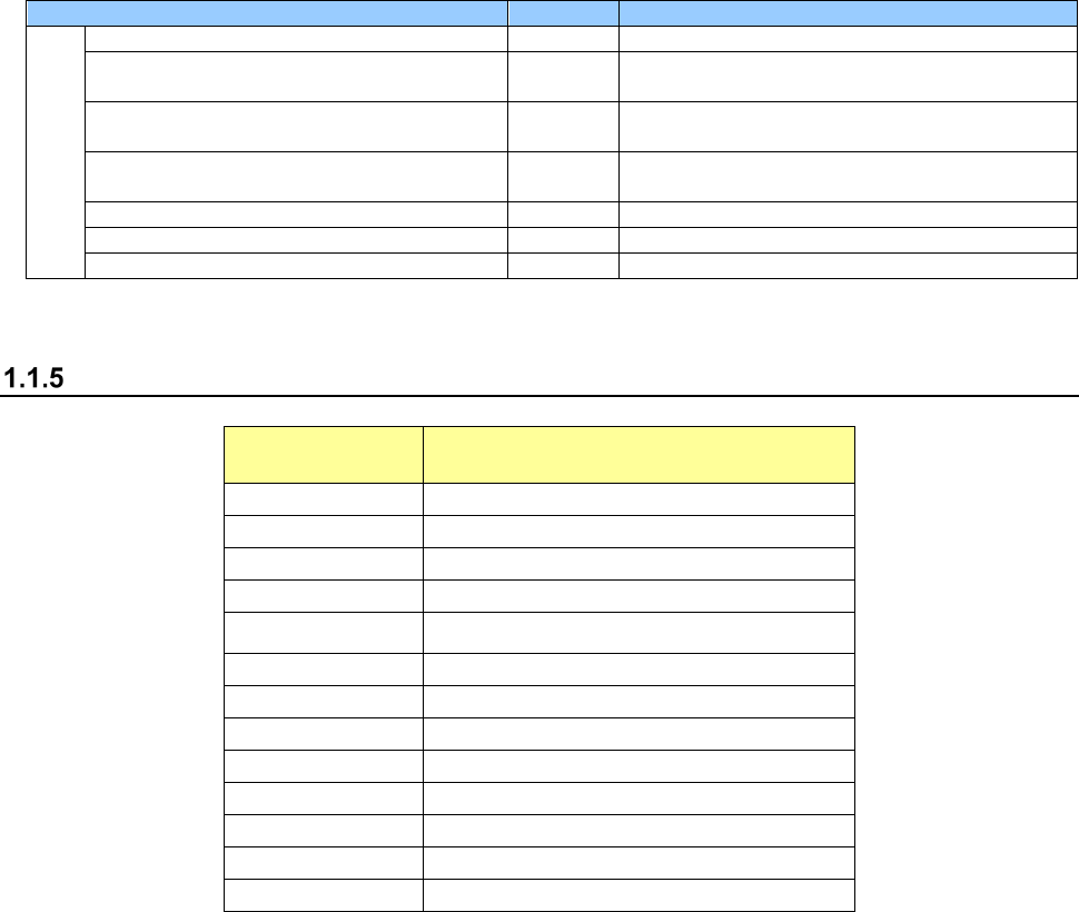
Descriptions of the abbreviations used in this Manual
Abbreviation Meaning
ATC
(Auto Tool Changer)
CVS
(Component Verification System)
DTS
(Dual Tray Server)
ETF
(Electric Tape Feeder)
HMS (Height Measurement System)
IFS-NX
(Intelligent Feeder System)
LNC
(Laser align New Concept)
MTC
(Matrix Tray Changer)
MTS
(Matrix Tray Server)
OCC
(Offset Correction Camera)
PWB
(Printed Wiring Board)
S-VCS
(Scanning Vision Centering System)
VCS
(Vision Centering System)