RS-1_instruction manual.pdf - 第50页
Part 1 B asic O peration Chapter 1 Overv iew of the Machine 1- 32 I nterface w ith external d evi ces ① is a SMEMA conn ector . T o use the m ain u nit onlin e and connec t it to anothe r device, the board transport dire…
Part 1 Basic Operation Chapter 1 Overview of the Machine
1-31
Electrical specifications
(1) Control Systems
Item
Control system
Resolution
X-Y Semi-closed-loop control system with the AC serve motor 0.0001 mm
Models Control system Resolution
Z
Semi-closed-loop control system with the AC serve motor
0.0305 μm
θ
0.00137°
ZA 0.0299 μm
(2) Main CPU
Intel® Celeron
(3) Display
Support of a 15-inch touch panel (SVGA mode LCD panel)
(4) Data and program input/output
You can manually enter data with the software ten-key of a touch panel.
By using USB flash memory, you can transfer data such as production program.
When this is connected to Floor productivity improvement support system, data communication
can be performed by LAN interface.
(5) USB port
External drives or external storage devices can be connected via the USB port.
(6) Power requirements
Voltage (three-phase) : 200 V AC (standard)
: 220 V, 240 V, 380 V, 400 V, 415 V AC (option)
Allowable voltage range : ± 10 % (for the rated voltage)
Apparent power : 2.2 kVA
Frequency : 50/60 Hz
Size of the primary-side power cable : 5.5 mm
2
or more
Size of the protective grounding lead wire : 5.5 mm
2
or more
(7) Protection at power failure (Uninterruptible power-supply system)
This machine is equipped with the ATX power supply working as uninterruptible power supply to
prevent data from being damaged or lost due to power failure.
Batteries are used as the back-up power supply of the ATX power supply, so the ATX power
supply is designed to stop the system before these batteries run down. Therefore, even during
power failure, the system can be terminated safely so that any data cannot be damaged or lost
even when a power failure occurs.
Part 1 Basic Operation Chapter 1 Overview of the Machine
1-32
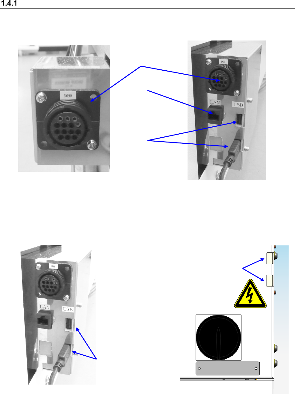
Interface with external devices
① is a SMEMA connector. To use the main unit online and connect it to another device, the board
transport direction, “left to right” or “right to left,” of both should be the same with each other.
② is an Ethernet connector (8-pin modular connector).
Left side of the front of the main unit
Right side of the front of the main unit
③ are USB connectors (two). In and before Rev. C system, this item is installed in the same
position as ② in the lower right side of the front. In and after Rev. D system, it is installed on
the power switch in the right side of the front.
(If you use a flash-memory device, be sure to remove it after finishing operating the machine.)
Right side of the front of the main unit
(in and after Rev. C)
Right side of the front of the main unit
(in and after Rev. D)
③ (In and before Rev. C)
①
②
③
③ (In and after Rev. D)
Part 1 Basic Operation Chapter 1 Overview of the Machine
1-33
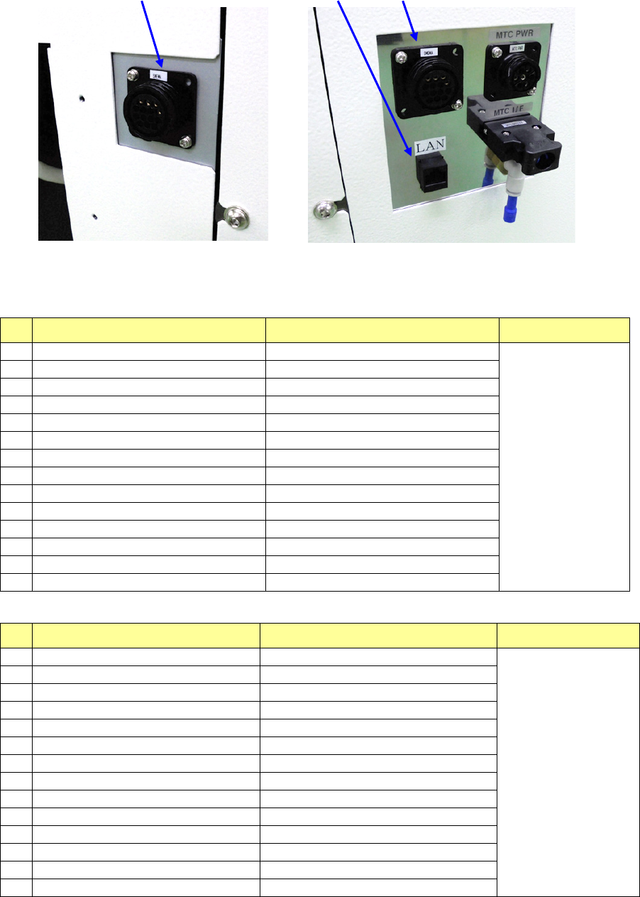
①
②
①
Left side of the front of the main unit (XL)
Right side of the front of the main unit (XL)
List of connectors on the left side panel
No.
Signal name (left to right) Signal name (right to left) Connector used
1
READY OUT
+
READY IN
+
AMP
206043-1
Connection of
the cable end
206044-1
2
READY OUT
-
READY IN
-
(GND)
3
BOARD AVAILABLE IN
+
BOARD AVAILABLE OUT
+
4
BOARD AVAILABLE IN
-
(GND)
BOARD AVAILABLE OUT
-
5
N.C.
N.C.
6
N.C.
N.C.
7
N.C.
N.C.
8
N.C.
N.C.
9
N.C.
N.C.
10
N.C.
N.C.
11
N.C.
N.C.
12
N.C.
N.C.
13
N.C.
N.C.
14
N.C.
N.C.
List of connectors on the right side panel
No.
Signal name (left to right) Signal name (right to left) Connector used
1
READY IN
+
READY OUT
+
AMP
206043-1
Connection of
the cable end
206044-1
2
READY IN
-
(GND)
READY OUT
-
3
BOARD AVAILABLE OUT
+
BOARD AVAILABLE IN
+
4
BOARD AVAILABLE OUT
-
BOARD AVAILABLE IN
-
(GND)
5
N.C.
N.C.
6
N.C.
N.C.
7
N.C.
N.C.
8
N.C.
N.C.
9
N.C.
N.C.
10
N.C.
N.C.
11
N.C.
N.C.
12
N.C.
N.C.
13
N.C.
N.C.
14
N.C.
N.C.