RS-1_instruction manual.pdf - 第468页
Part 1 B asic O peration Chapter 4 Cr eating a Produc tion Progra m 4- 133 All feeders c an be arrang ed on only one side giving priority to the side. I n case all the number of feed ers to be used cannot be p ut in the …
Part 1 Basic Operation Chapter 4 Creating a Production Program
4-132
b) Auto assign all data:
Ignore the specified feeder layout and optimize the whole feeder layout.
Once you execute the optimization function, its result will be reflected in the “Side” filed of
the “Pick” data screen also. To retry optimization from the beginning after data editing is
finished after this, select "Distribute all." To perform additional layout for only changed
portions, select "Distribute items in the "Auto selection" status."
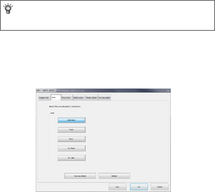
(2) "Area" option
Specify the area for the feeder layout.
The default selecting state and the area you can select vary depending on existence of a “rear
component supply device” option.
<Rear component supply device option>
Enabled: All buttons from the <Both sides> to <Prf. Rear> can be selected. (Default: <Both
sides>)
Disabled: Only the button <Front> can be selected. (Default: <Front>)
Area
1) Both sides:
Feeders are arranged into the feeder banks of all areas. For ordinary production, select
this. Because there is no limitation on optimization, the layout is advantageous to the tact.
2) Front:
Feeders are arranged in only the feeder bank on the front side.
3) Rear:
Feeders are arranged in only the feeder bank on the rear side.
All feeders can be arranged on only the front side or rear side.
If feeders are provided in the overall change table in advance, the time up to the next start of
production can be shortened. This makes a layout that makes much of the workability. In
case all the number of feeders to be used cannot be put in the bank of one side, this item
cannot be used.
4) Pri: front:
The feeders are arranged giving priority to the feeders on the front side.
5) Pri: rear:
The feeders are arranged giving priority to the feeders on the rear side.
Part 1 Basic Operation Chapter 4 Creating a Production Program
4-133
All feeders can be arranged on only one side giving priority to the side. In case all the
number of feeders to be used cannot be put in the bank of one side, the other side also can
be used.
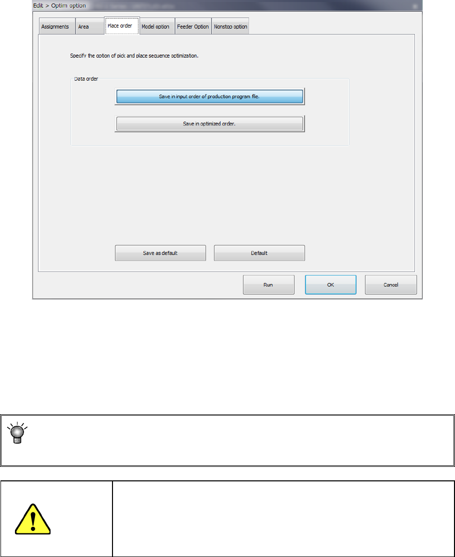
(3) "Placement order" option
Specify the placement data order: use the input order or change it according to the optimized
result.
Data order
a) Assign in input order of production program File
Placement data will be displayed in entry order (that is, not changed at all).
b) Assign in optimized order
Placement data will be displayed in the optimized order.
You can display the optimized order of placement order by selecting the [Optimization]
― [Divided placement data] commands from the menu also. (You cannot edit any data
on this screen.)
CAUTION
"Assign in optimized order" is a function for editing the optimized data
(optimization result can be referred to, but cannot be edited).
However, once this function is executed, the data in order of the
original date entry will be deleted. Therefore, back up the data before
executing this function.
Part 1 Basic Operation Chapter 4 Creating a Production Program
4-134
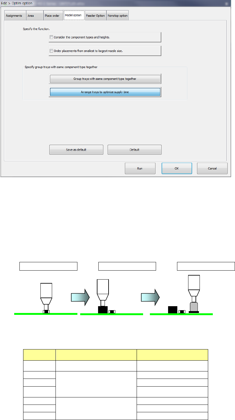
(4) Model option
1) Consider the component types and heights
When you check this check box, the system specifies the component layer with considering
the component height automatically to create a program that places components in high
density (that is, places components adjacently).
When you check this check box actually, the system places components in the following
order:
<Component placement by considering the component type and component height>
Placement order ① Placement order ② Placement order ③
<Relation between the component placement priority and the component type and height>
As indicated with “Priority” in the table below, components other than aluminum electrolytic
capacitor is prioritized.
Priority Component type Component height (mm)
1 Square chip resistor
0 < t ≦ 0.25
2
Square chip resistor
Components other than Elec.
Cap. (aluminum electrolytic
capacitor)
0
<
t
≦
5.5
3
5.5
<
t
≦
12.0
4
12.0 < t
5
Elec. Cap. (aluminum
electrolytic capacitor)
0
<
t
≦
5.5
6
5.5
<
t
≦
12.0
7
12.0
<
t