RS-1_instruction manual.pdf - 第370页
Part 1 B asic O peration Chapter 4 Cr eating a Produc tion Progra m 4- 35 4.3.4 Placement data Enter inform ation on the coordinat es of po si tions o n w hich the sy stem is to place comp onents . For a multi - pl ane P…
Part 1 Basic Operation Chapter 4 Creating a Production Program
4-34
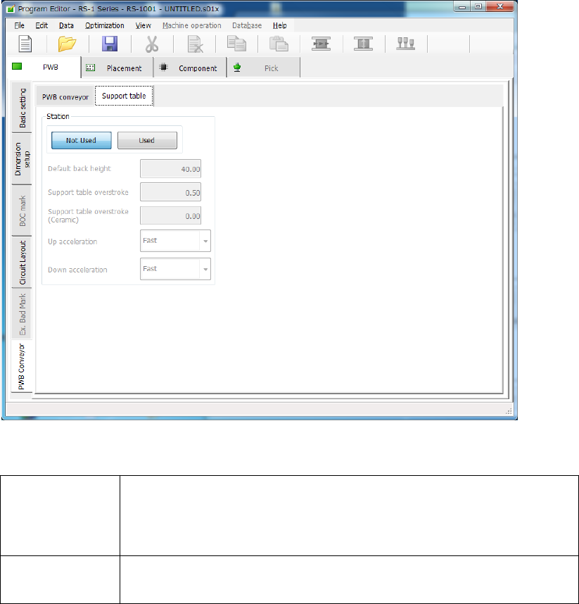
(2) “Support table” screen
If you select the “Support table” tab when the “PWB Conveyor” tab is selected, the following
screen appears.
1) Not Used/Used
Select whether to use the settings in the “Left station” group/“Right station” group or not.
Not Used
Select this radio button if you do not use the settings made in the
“Left station” group or the “Right station” group respectively.
The system operates according to the settings made with the main
unit(“Machine setup” – “Set contents of transport”).
Used
Select this radio button if you are to use the settings made in the
“Left station” group or the “Right station” group respectively.
2) Default back height
This item sets the lower limit of the support table for moving down a board. The allowable
value range is from 5.0 to 40.0 (mm).
3) Support table overstroke
4) Support table overstroke (Ceramic)
Enter an offset value to be applied when the support table moves up.
The support pin holds a board upwards by the value set in this field.
The allowable value range is from 0.0 to 5.0 (mm).
5) Up acceleration
Set the accelerated speed to be applied when the support table moves up.
6) Down acceleration
Set the accelerated speed to be applied when the support table moves down.
Part 1 Basic Operation Chapter 4 Creating a Production Program
4-35
4.3.4 Placement data
Enter information on the coordinates of positions on which the system is to place components.
For a multi-plane PWB, enter the information on the “reference circuit.”
Number of component placements:
Number of placement points: Regardless of single-circuit PWB or
multi-circuit PWB, up to 10,000 points can be entered in total.
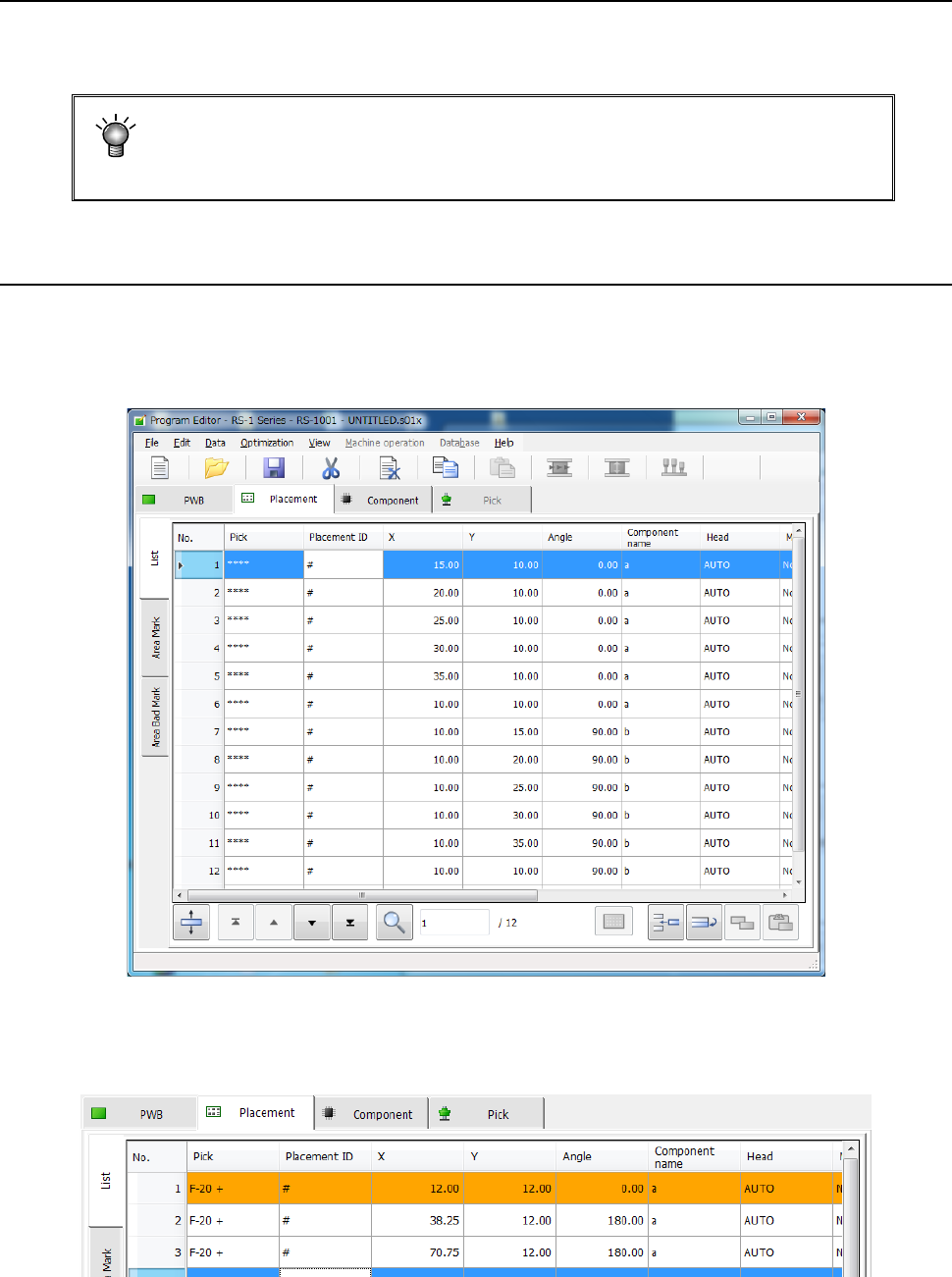
4.3.4.1 Viewing the placement data screen
When you select the “Placement” tab displayed on the screen after creating PWB data completely,
the “Placement” data screen for creating Placement data (the following figure is an example
indicating that Placement data was already created) appears on the screen.
When any skip setting (including component data skip setting) is performed, the indication is
changed into orange as shown below.

Part 1 Basic Operation Chapter 4 Creating a Production Program
4-36
4.3.4.2 Creating Placement data
Enter a value in each of the “Component ID,” “X,” “Y, ” “Angle” and “Component name” fields. The
corresponding initial value is automatically entered in the other fields (the “Head,” “Mark,” “Area
Bad Mark,” “Skip,” “Trial” and “Layer” fields). Change the value(s) in these fields when necessary
only.
Note that each coordinate indicates the distance from the “board reference position” determined
on the “PWB” data screen (“Circuit origin” of the reference circuit for a multi-plane PWB).
(1) Pick
The component pick-up position set when you open the “Placement” data list screen is shown
here.
An asterisk mark (“*”) appears when the component pick-up position is not determined.
When there are multiple feeders for the same component, the pick position is determined by
executing optimization.
When there are not multiple feeders for the same component, the pick position is determined
without executing optimization.
When there are two or more pick data records for the same component type, the pick-up position
of the first one appears, and a plus mark (“+”) appears to the left of this position. You cannot
enter any value in this field.
(2) Placement ID
Enter the placement location as a reference notation. Therefore, this does not have any
influence over placement.
When this item is entered, the default value is applied to each item in which the default value can
be entered, and then displayed.
In addition, this item can be omitted by clicking another item (such as an X coordinate) without
entering any data.
In this case, a "#" mark will be entered here automatically.
(3) X and Y
As the input method, numeric input, teaching input, and data conversion from Flexline CAD are
available.
* Be sure to perform a BOC alignment operation before teaching it. When BOC alignment is not
executed, put a checkmark in the check box “Align placement position with BOC” on the
“Teaching” tab of the “Operation option” screen.
As a coordinate, enter the distance from the “PWB origin” (or circuit origin for a multi-plane PWB)
determined on the “PWB” data screen to the component placement position (center of a
coordinate).
・ Entry of an absolute position:
Enter a numeric value from a keyboard.
You can assign a sign, “+” or “–“ (minus) for a value.
・ Entry of a relative position:
When you enter “++” before a numeric value, the entered value is added to a value
displayed in the field on which the cursor is located.
When you enter “—“ before numeric value, the entered value is subtracted from a value
displayed in the field on which the cursor is located.
When you enter “+=” before a numeric value, the entered value is added to a value in the
field one line above the field on which the cursor is located.
When you enter “-=” before a numeric value, the entered value is subtracted from a value
displayed in the field one line above the field on which the cursor is located.
Note: You cannot enter a space between two symbols, ++, --, += or -=.