RS-1_instruction manual.pdf - 第496页
Part 1 B asic O peration Chapter 4 Cr eating a Produc tion Progra m 4- 161 An examp le of the resu lt of execution of the [Mat rix copy] com mand for the Placem ent data is show n b elow. Pla cem ent ID X Y Angle Compone…
Part 1 Basic Operation Chapter 4 Creating a Production Program
4-160
4.5.1.8 Matrix copy
Screen
Function
PWB data
Basic setting screen
This command cannot be used.
Dimension setup screen
Circuit Layout screen
Ex. Bad Mark screen
PWB Conveyor screen
Placement data
List screen
See the descriptions below for how
to use this command.
Area Mark screen
This command cannot be used.
Area Bad Mark screen
Component data
List screen
This command cannot be used.
Form screen
Pick data
List screen
See the descriptions below for how
to use this command.
Form screen This command cannot be used.
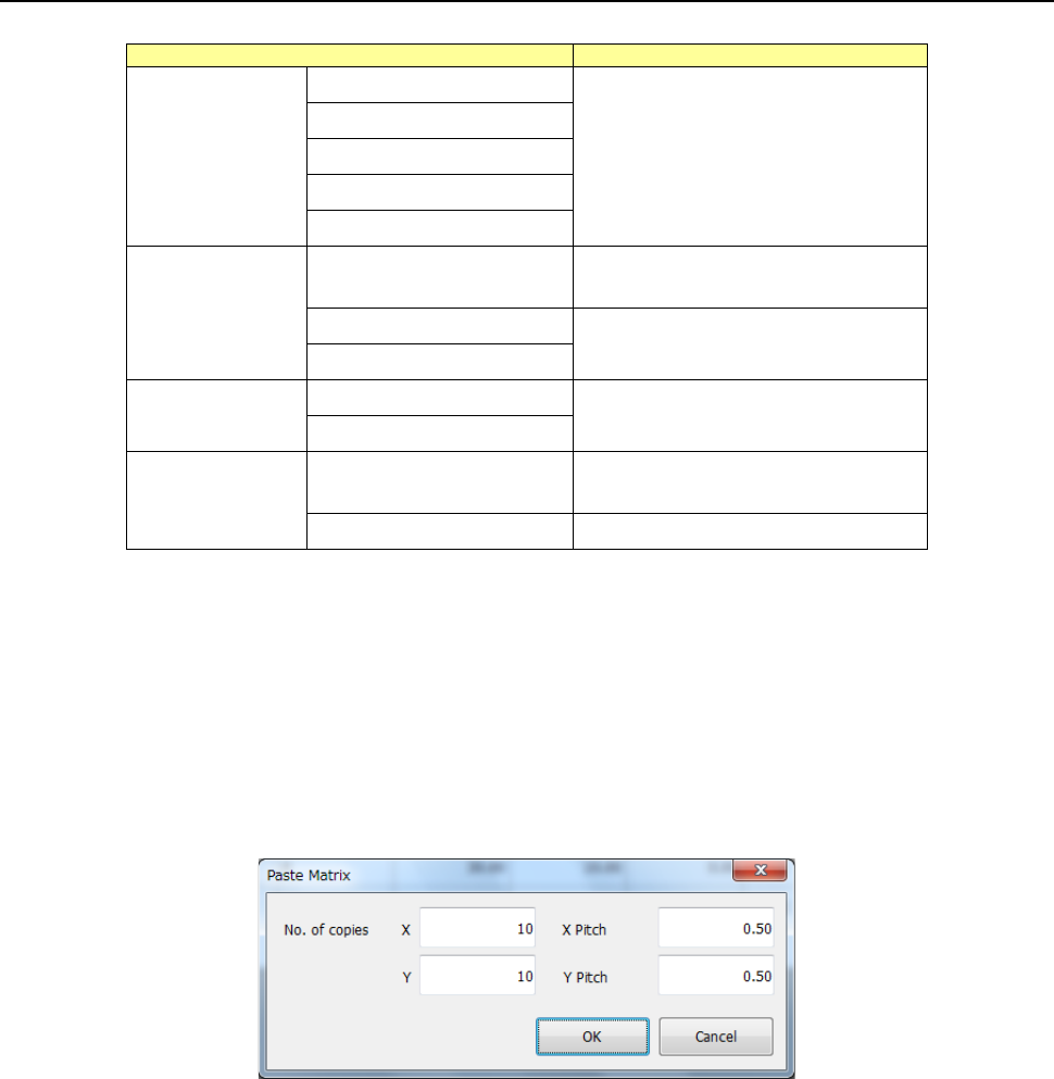
As for the Placement data, this command inserts data that has been loaded into the memory buffer
with the [Cut] or [Copy] command before the cursor. When you specify the “X” and “Y” fields of
“No. of copies” and the “X Pitch” and “Y Pitch” fields, the system allows you to copy the data in a
matrix with adding or subtracting the entered values to/from the component placement position in
the X direction and that in the Y direction.
After you execute the [Matrix Copy] command for the Placement data, all the placement IDs are
changed to “#.”
If the memory buffer is empty, you cannot select this command for the Placement data.
After you execute the [Matrix Copy] command for the Placement data, all the placement IDs are
changed to “#.”
No. of copies X
: Specify the number of times the system will copy data in the X
direction.
“1” is set by default.
No. of copies Y
: Specify the number of times the system will copy data in the Y direction.
“1” is set by default.
X Pitch
: Specify the amount to increment or decrement a value of the component
placement position in the X direction. “0.000” is set by default.
Y Pitch
: Specify the amount to increment or decrement a value of the component
placement position in the Y direction. “0.000” is set by default.
OK
: This button pastes the data
Cancel
: This button cancels the paste operation.
Part 1 Basic Operation Chapter 4 Creating a Production Program
4-161
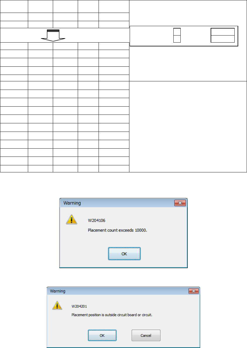
An example of the result of execution of the [Matrix copy] command for the Placement data is
shown below.
Placement
ID
X
Y
Angle
Component
name
R1
5.000
10.000
45.000
1608-A
R2
10.000
10.000
0.000
1608-A
No. of copies X
3
X Pitch:
0.500
No. of copies Y
1
Y Pitch:
1.000
R1
5.000
10.000
45.000
1608-A
R1
10.000
10.000
0.000
1608-A
#
5.500
10.000
45.000
1608-A
- The copied block is inserted above
the specified line.
- All placement IDs are set to “#.”
#
10.500
10.000
0.000
1608-A
#
6.000
10.000
45.000
1608-A
#
11.000
10.000
0.000
1608-A
- The input focus is positioned in the
first “Placement ID” column of the
inserted block.
#
6.500
10.000
45.000
1608-A
#
11.500
10.000
0.000
1608-A
#
5.000
11.000
45.000
1608-A
#
10.000
11.000
0.000
1608-A
#
5.500
11.000
45.000
1608-A
#
10.500
11.000
0.000
1608-A
#
6.000
11.000
45.000
1608-A
#
11.000
11.000
0.000
1608-A
#
6.500
11.000
45.000
1608-A
#
11.500
11.000
0.000
1608-A
If the number of data records exceeds the maximum number, the message like one shown below
appears on the screen, and the copy operation is aborted. In this case, no data is copied.
If the placement position is outside the board or the circuit, the message like one shown below
appears on the screen.
OK: The system continues copying data. A mark indicating that the placement
position is outside the regulated range is appended to the copied data.
Cancel: The system aborts the copy operation.
Part 1 Basic Operation Chapter 4 Creating a Production Program
4-162
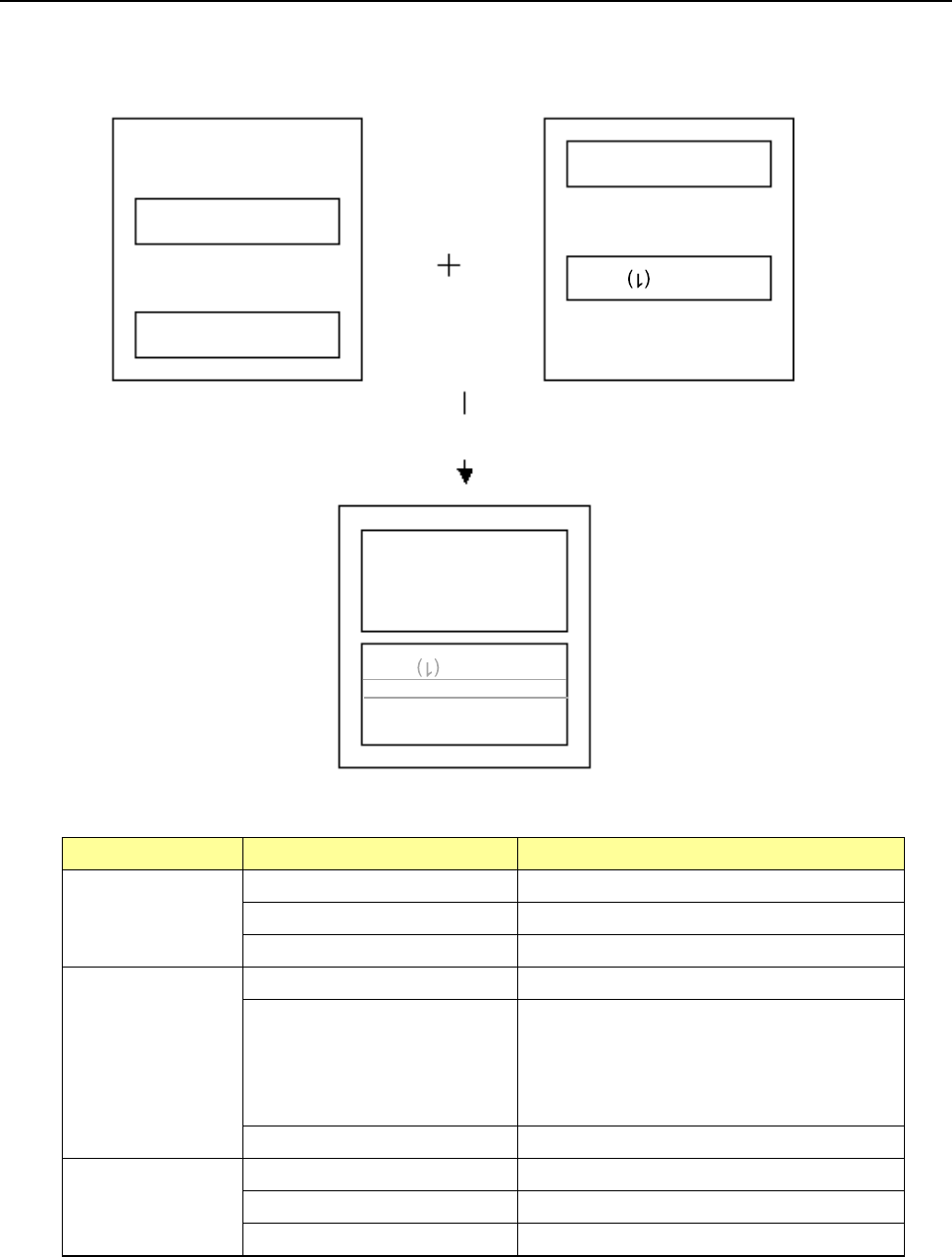
4.5.1.9 Production program copy
This function allows two or more matrix circuits to be defined within the same board.
Two or more matrix circuits are defined within the same board.
Two or more circuits are arranged, and the positions of the arranged circuits are corrected with
area marks, and then placed on a board.
Source PWB Destination PWB Result
Single-plane PWB Single-plane PWB Single-plane PWB
Multi-plane matrix PWB Single-plane PWB
Multi-plane non-matrix PWB Single-plane PWB
Multi-plane matrix
PWB
Single-plane PWB Single-plane PWB
Multi-plane matrix PWB Single-plane PWB or multi-plane matrix PWB
When the number of divisions is equal to the
pitch between the consecutive circuits, and
the offset theta is 0 or 180 degrees, the board
is copied as a multi-plane matrix PWB.
Multi-plane non-matrix PWB Single-plane PWB
Multi-plane
non-matrix PWB
Single-plane PWB Single-plane PWB
Multi-plane matrix PWB Single-plane PWB
Multi-plane non-matrix PWB Single-plane PWB
If there are two or more board configuration candidates to be arranged after copy, or if two or more
circuits are overlapped with one another after copy, the system asks you how circuits will be
arranged on the board.
Source production program
Execution of the [Production program copy] command
Side A (2)
Side A (1)
Destination production program
Side B
Side B
(2)
Side B
Side A (1)
Reference circuit