RS-1_instruction manual.pdf - 第1023页
Part 2 D etaile d Descript ion of E ach Functi on Chapter 12 Handling th e Optional Device s 12 - 139 ④ N otes on c ompone nt dime nsion check When you specify the “ Dimension check ” items, be careful to enter the “ S t…
Part 2 Detailed Description of Each Function Chapter 12 Handling the Optional Devices
12-138
(2) Creating Component data
◇ Example for creating Component data
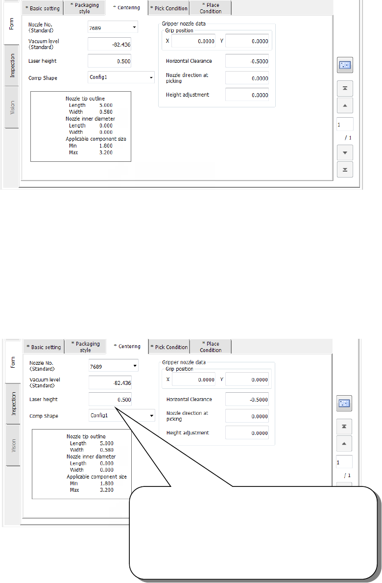
① Setting the nozzle number
② Entering information for controlling a component position picked up by a gripper nozzle
See ⑤ “Gripper nozzle data” of Section 4.3.5.2.3 (3)“Centering” for details.
③ Laser pos. (position)
Be careful to enter this setting item when you use a gripper nozzle.
Normally, enter the distance from the top of a component to the surface on which laser
beam impinges in the “Laser pos.” field of a nozzle. However, when you use a gripper
nozzle, enter the distance laser is beamed by regarding the tip of the nozzle that is
located at the fixed arm as a reference position.
Specify the distance from the tip of a nozzle to the surface
on which laser beam impinges.
Setting guide: - (component height – 3.5 mm) / 2
Make trivial adjustments of this value
according to a lead position.
Example shown on this screen: - (3.8 – 3.5) / 2
= - 0.15
Part 2 Detailed Description of Each Function Chapter 12 Handling the Optional Devices
12-139
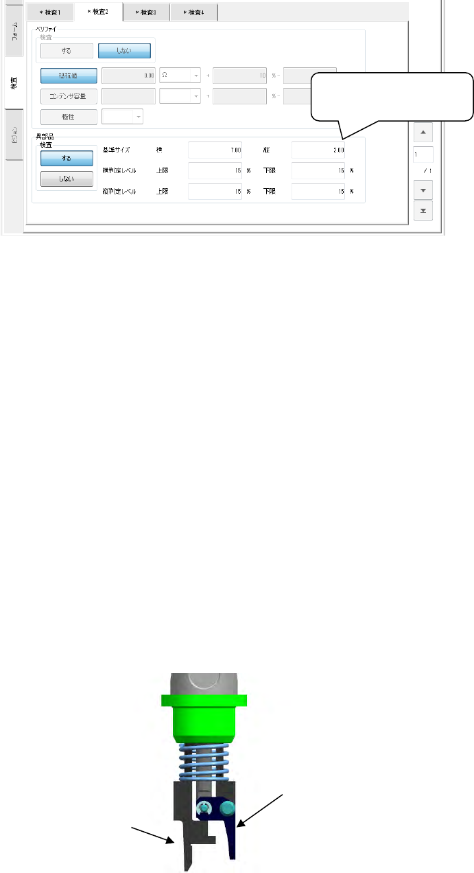
④ Notes on component dimension check
When you specify the “Dimension check” items, be careful to enter the “Std. Size”
(reference size).
- The “Std. Size” means the size of the molded part on which laser beam is to impinge, and
it is different from the dimensions of a component including a lead.
(3) Pick Data
Pick data to be created when you use a gripper nozzle is the same as that for a standard
nozzle. Therefore, you do not have to perform teaching operation for the gripper arm
position and the height of the nozzle section against which the component topside should be
pushed.
- X and Y coordinates: the center of a component is used as the reference position. The
nozzle moves to the coordinates that are corrected with values entered into the “Grip
position,” “Horizontal clearance” and “Fixed arm offset.” Since the system picks up a
component according to the grip position including the length of the arm during production,
perform the teaching operation so that the tip of the gripper nozzle arm can be located
outside any side of a component. If you start the teaching operation with a camera and
switch the current head to another one during teaching, the corrected values are not
saved in pick data.
- Z coordinate: the tip of the nozzle (Height of an edge of the fixed arm = Height of the
normal nozzle) is used as a reference position.
Since the system picks up a component according to the grip position including the length
of the arm during production, perform the teaching operation so that the tip of the gripper
nozzle arm can be located on a level with the topside of a component.
(4) Direction in which a gripper nozzle is attached onto an ATC
View the ATC unit from its front, and install a gripper nozzle onto the ATC so that the fixed
arm of the gripper nozzle (① in the figure below) can be located on the rear, and the
swing arm (② in the figure below) can be located on the front.
Length of a component
including a lead
②
①
Part 2 Detailed Description of Each Function Chapter 13 Supplementary Information for
Creating a Production Program
13-1
Chapter 13 Supplementary Information for Creating a
Production Program
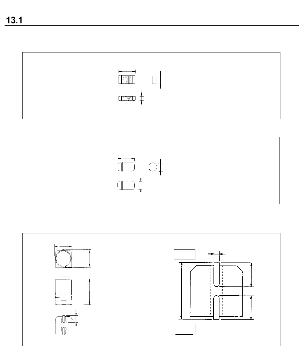
Examples of component dimensions
• Square chip (LED)
• MELF
• Aluminum electrolytic capacitor
Component height
Dimensions (horizontal)
Dimensions (Vertical)
Lead length
Lead length
Lead length
Dimensions
Dimensions (horizontal)
Dimensions (Vertical)
Component height
Dimensions (horizontal)
Dimensions (Vertical)
Component height
+ side
– side
Lead width