RS-1_instruction manual.pdf - 第642页
Pa rt 2 Detailed Des cription o f Each Function Chapter 6 G eneral - Purpose Visio n Component 6- 11 Creatin g an ext ended array dat a format When you select “ Exte nded array data format ” on th e init ial scr een for …
Part 2 Detailed Description of Each Function Chapter 6 General-Purpose Vision Component
6-10
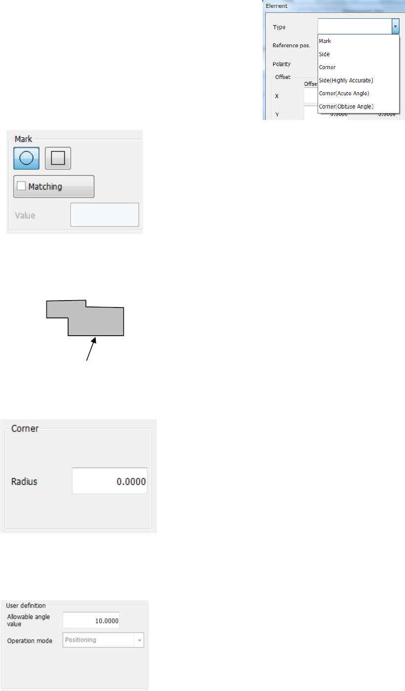
◎ When the radio button “Point” is selected on the
“Element Group” dialog box, the menu items
shown in the right figure can be selected from
the “Type” list.
• Mark
When you select “Mark” in the “Type” field, this screen
appears.
- Matching:
Specify the tolerant range of the similarity.
The higher value you specify, the more strictly the
system judges the similarity.
(The initial value is set to “600.”)
• Side
For a component whose element is irregular-shaped (other than a circle or square),
you can cause the system to recognize a component with its side.
The bottom side is the reference side. When you
use the right side, enter “90°” in the “Theta” field of
the “Offset” menu item displayed on the “First
element position” column. In the same manner,
enter “180°” for the top side or “270°” for the left side.
• Corner
When you select “Corner” in the “Type” field, this screen appears.
- Radius:
Enter the radius of the corner section.
For a right-angled corner, enter “0.”
The reference corner is the bottom left corner when the
component supply angle is 0°.
If you want to use the bottom right corner, specify “90°”
in the “Theta” field of the “Offset” menu item displayed
on the “First element position” column. In the same
manner, enter “180°” for the top right corner or “270°”
for the left top corner.
• User definition
This column is displayed when “User definition” is selected as the “Type.”
• Allowable angle value:
Unless “Direction” is specified in the “Operation mode”
field, enter the allowable angle deviation generated
during recognition here. The entered value is applied in
both directions: positive and negative directions.
(“10 degrees” is entered as the initial value.)
The operation mode can be set when you create a
user-defined element, and you cannot change it on this
screen.
Reference side
Part 2 Detailed Description of Each Function Chapter 6 General-Purpose Vision Component
6-11
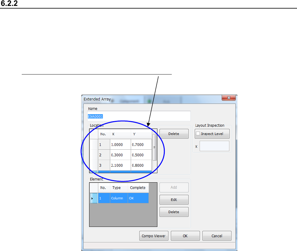
Creating an extended array data format
When you select “Extended array data format” on the initial screen for creating a general-purpose
vision component, the following dialog box appears on the screen.
The procedure for creating data is basically the same as that for the “Element group/ Element
format.” However, for an “Extended array data format,” specify the X and Y coordinates of an
element one by one.
Specify an element in the “Location” field one by one. Enter the X and Y coordinates viewed
from the center of a component.
* Up to 256 locations can be set.
Part 2 Detailed Description of Each Function Chapter 6 General-Purpose Vision Component
6-12
Component Viewer 6.3
The Component Viewer allows you to display the created data on a general-purpose vision
component graphically.
Opening “Component Viewer” 6.3.1
The operating method and the contents of data to be displayed on “Component Viewer” vary
depending on the screen from which “Component Viewer” is started.
Screen from which “Component
Viewer” is opened
For editing element data Contents of display
Opening from the Vision Form screen “Component Viewer” must be closed. All element groups are displayed.
Opening from the Element Data screen
“Component Viewer” does not need to
be closed.
All element groups are displayed.
Opening from the Element Group
screen
Only the current element group is
displayed.
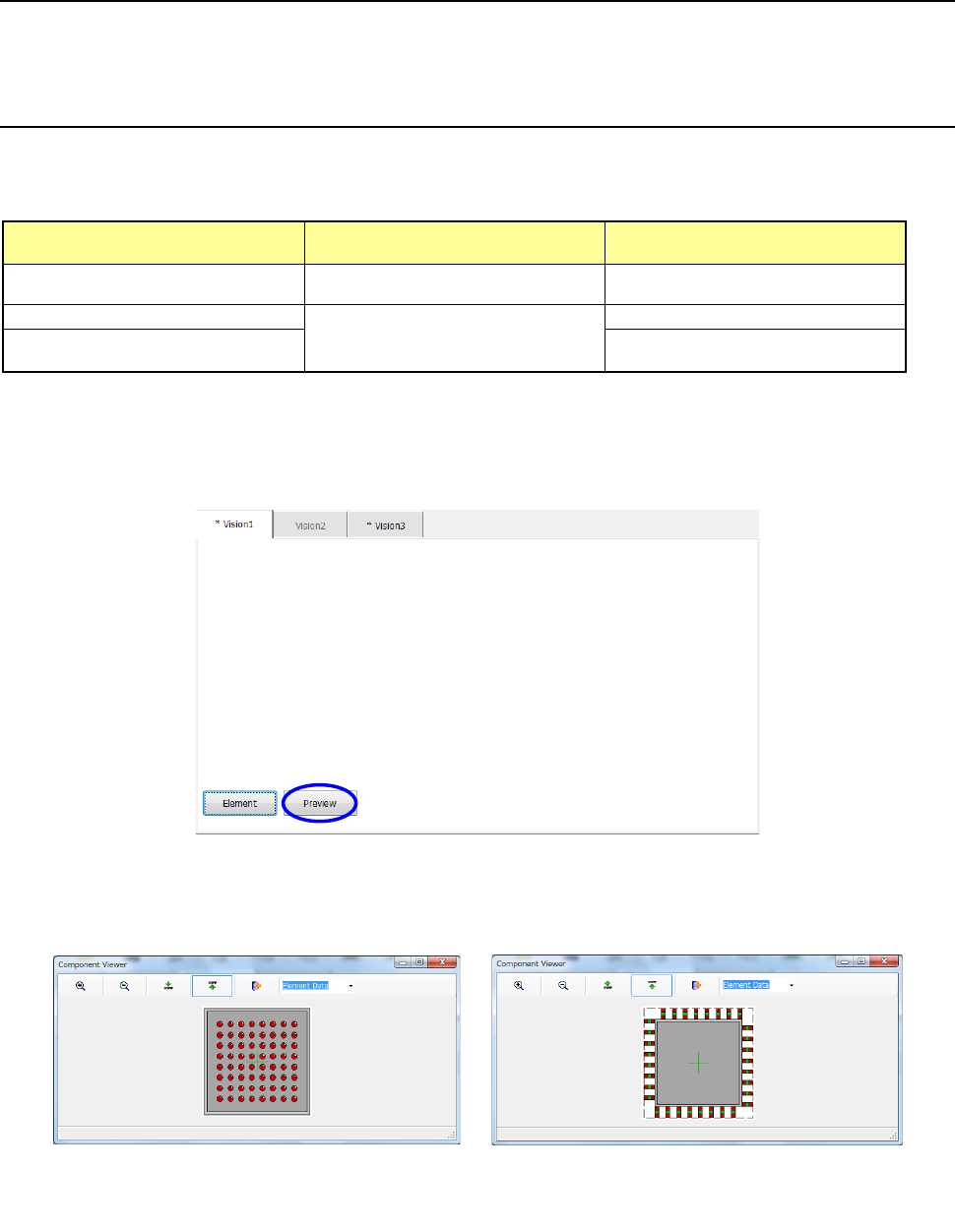
1) Opening from the Vision Form screen
When a general vision component is displayed on the Vision Form screen, the <Preview>
button is displayed on the Vision Form screen.
− Touching the <Preview> button displays the following dialog box.
Example of the
ball component screen
Example of the
lead component screen