RS-1_instruction manual.pdf - 第44页
Part 1 B asic O peration Chapter 1 Overv iew of the Machine 1- 26 (2) P lace ment accur acy ( θ ) Compon ent placeme nt accuracy θ (whe n a compo nent is reco gnized with laser) Unit: ° Component siz e * This size indica…
Part 1 Basic Operation Chapter 1 Overview of the Machine
1-25
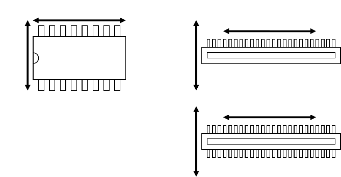
Note 3: Right angles to a lead and the direction parallel to a lead described for the accuracy of an SOP,
unidirectional lead connector, and bidirectional lead connector and a component whose image is
divided to be recognized are shown in the figure below.
Note 4: Since a BGA component position cannot be corrected with recognition of its image under the
following conditions, the component placement accuracy cannot be guaranteed.
①
Contrast between a solder ball and the surface of a board to which the solder ball is applied is
not clear enough. (Excluding a BGA whose body is ceramic)
②
A pattern whose thickness is the same as the diameter of a solder ball is connected to the ball,
and the ball cannot be recognized separately.
③
There is a through-hole or similar hole whose diameter is the same as that of a solder ball on
the board to which the ball is applied.
Right angles to a lead
Direction parallel to a lead
Right angles to a lead
Right angles to a lead
Direction parallel
to a lead
Direction parallel
to a lead
Part 1 Basic Operation Chapter 1 Overview of the Machine
1-26
(2) Placement accuracy (θ)
Component placement accuracy
θ (when a component is recognized with laser)
Unit: °
Component size
* This size indicates the
distance between two
terminals.
LNC120-8 Remarks
03015 square chip - ±6
Note: If a 03015 component
cannot be recognized with laser
stably due to its shape (for example,
if a string art image is not displayed
normally), use a VCS (10-mm field
of view camera) (optional).
0402 square chip
-
±5
0603 square chip
-
±3
1005 square chip
-
±2.5
1608 or larger square chip
-
±2
MELF
-
±3
SOT
-
±3
Aluminum electrolytic capacitor
-
±10
SOP, TSOP
50 mm or less
±0.30
20 mm or less
±0.33
10 mm or less
±0.67
PLCC
-
±0.52
SOJ
-
±0.52
QFP (Pitch: 0.8 or more)
50 mm or less
±0.33
30 mm or less
±0.37
20 mm or less
±0.44
QFP (Pitch: 0.65)
50 mm or less
±0.30
10 mm or less
±0.33
BGA
(Distance between the opposite
sides of the ball outer
circumference)
50 mm or less
±1.23
20 mm or less ±1.28

Part 1 Basic Operation Chapter 1 Overview of the Machine
1-27
Component placement accuracy
θ (when a component is recognized with a VCS)
Unit: °
Component size
* This size indicates the distance
between two terminals.
VCS recognition
Aluminum electrolytic capacitor
-
±0.6
SOP, TSOP
50 mm or less
±0.12
40 mm or less
±0.15
30 mm or less
±0.21
20 mm or less
±0.31
10 mm or less
±0.65
PLCC
-
±0.3
SOJ
-
±0.5
QFP
(Pitch: 0.65 or more)
50 mm or less
±0.05
40 mm or less
±0.07
30 mm or less
±0.1
20 mm or less
±0.2
10 mm or less
±0.3
QFP
(Pitch: 0.5, 0.4 and 0.3)
50 mm or less
±0.05
40 mm or less
±0.07
30 mm or less
±0.1
20 mm or less
±0.2
10 mm or less
±0.3
Bidirectional lead connector
(Pitch: 0.5)
50 mm or less
±0.05
40 mm or less
±0.07
30 mm or less
±0.1
20 mm or less
±0.2
10 mm or less
±0.3
Unidirectional lead connector
(Pitch: 0.5)
50 mm or less
±0.12
40 mm or less
±0.15
30 mm or less
±0.21
20 mm or less
±0.31
10 mm or less
±0.65
Component whose image is
divided to be recognized.
150 mm or less
±0.065
100 mm or less
±0.09
75 mm or less
±0.1
50 mm or less
±0.2
30 mm or less
±0.3
BGA
(Distance between the opposite
sides of the ball outer
circumference)
50 mm or less
±0.1
40 mm or less
±0.12
30 mm or less
±0.18
20 mm or less
±0.3
FBGA
(Distance between the opposite
sides of the ball outer
circumference)
50 mm or less
±0.1
40 mm or less
±0.12
30 mm or less
±0.18
20 mm or less
±0.3
Outline-recognized component
50 mm or less
±0.4
40 mm or less
±0.45
30 mm or less
±0.55
20 mm or less
±0.85
0201 square chip
-
±8
03015 square chip
-
±6
0402 square chip
-
±5
0603 square chip
-
±3
1005 square chip
-
±2.5
1608 or larger square chip
-
±2