RS-1_instruction manual.pdf - 第712页
Part 2 D etaile d Descript ion of E ach Functi on Chapter 8 Machine S etup 8-4 8.3 Setting Items The setting ite ms for Machine set up are div ided into t he following gro ups. No. Operation gr oup Indicate d button Sett…
Part 2 Detailed Description of Each Function Chapter 8 Machine Setup
8-3
8.2.2 Exit
When you click the Close button [x] in the upper right part of the screen, press the End button in
the information area, or press the shortcut key, Machine setup is finished.
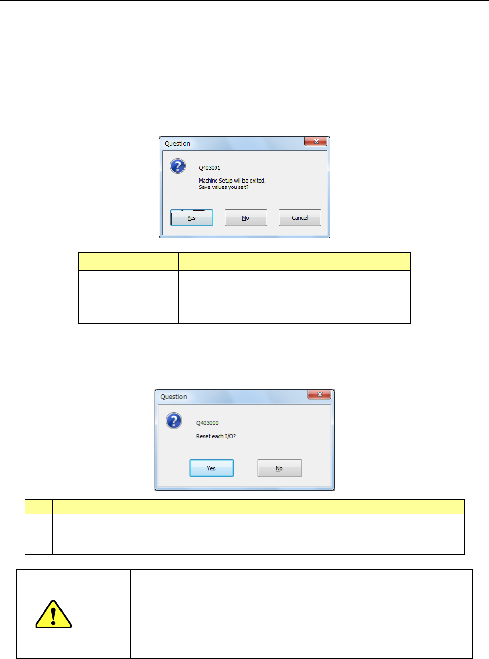
(1) Saving the setting values
Each screen of the setting groups is equipped with the push buttons <OK> and <CANCEL>.
Even though you press the <OK> button, the system does not save any data on the SSD at
this time. The system displays the “Question” dialog box that asks you whether to save the
setting values or not if you change any of the setting values on the “Machine Setup” screen.
When you select the <Yes> button, the changed values are saved on the SSD.
No. Button Action
1 Ye s Saves the setting data onto the SSD.
2 No Cancels the setting data.
3 Cancel Cancels the Exiting Application command.
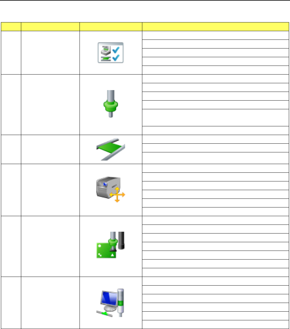
(2) Setting the safety direction of each I/O
After you select the process for quitting the Machine Setup utility, the system displays the
“Question” screen for setting the safety direction of each I/O on the screen.
No.
Button selection
Process
1 Ye s Sets the safety direction of each I/O and quits the Machine Setup utility.
2 No The system returns to the “Machine Setup” screen.
CAUTION
When you click the <Yes> button, the axes move, and the system
starts setting each I/O safety direction.
Before clicking the <Yes> button, be sure to check to see if there is
no one who operates the inside of the machine. To avoid a risk of
injury, do not put your hands inside the machine nor move your face
or head close the machine while the machine is operating.
Part 2 Detailed Description of Each Function Chapter 8 Machine Setup
8-4
8.3 Setting Items
The setting items for Machine setup are divided into the following groups.
No.
Operation group
Indicated button
Setting item (operation)
1 Device enable
Head
Base
Conveyor
MTC/MTS
VCS
2 Nozzle
Registered nzl. No. table
Read nzl. data
ATC nozzle setup
Vacuum value without nozzle
Vacuum value without nozzle
* Available with an RS-1R only.
ATC Setting * Available with an RS-1R only.
3 Conveyor
Conveyor setting
Support table
Shape clamp position adjustment
4 Position setting
Component
reject position
IC collection belt position
Head wait position
MTS position offset
MTC shuttle pick position
5 Function setting
Pick error condition setting
Mark recognition speed setting
Solder Print Misalignment Correction
Pre-pick feed setting
Head height setting
Nozzle sliding fail check
Splicing setup
6 Unit setting
Signal light
Bad mark teaching
Superimpose setting
Line connection
Coplanarity
Verification
Part 2 Detailed Description of Each Function Chapter 8 Machine Setup
8-5
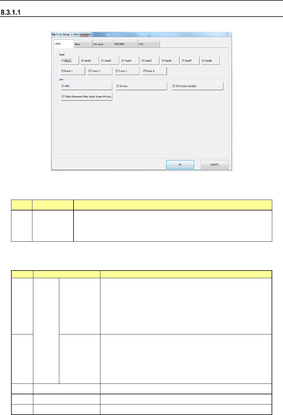
8.3.1 Device enable
Head
When you select “Head,” the following screen appears.
When you click each tab, you can specify each of “Head,” “Base” “Conveyor,” “MTS” and “VCS.”
(1) Setting items
No. Item Description
1 Head
Specify whether to use a device or not.
If you set one device not to be used on this tab, when it malfunctions the
system can continue picking up and placing components without
changing data of a production program.
1) For the case where the production program requires the above unit to complete placement,
the following table shows whether placement is actually performed or not.
No.
Unit
Production operation
1
Head
Head1
Head2
Head3
Head4
Head5
Head6
Head7
Head8
When there are components to be placed in these heads, the
alternate head places them if the alternate head is available
and no head is specified.
If placement cannot be performed, an error occurs at
production pre-start check, resulting in no production. Modify
the production program.
Components are not assigned to these heads by optimization.
2
θ axis 1
θ axis 2
θ axis 3
θ axis 4
The θ axes of the head are controlled every two axes.
Therefore, when any θ-axis check box is checked off, the
corresponding heads shown below cannot be used.
θ axis 1: Head1, Head2
θ axis 2: Head3, Head4
θ axis 3: Head5, Head6
θ axis 4: Head7, Head8
3 HMS This function is just deleted, and placement is executed.
4 ZA axis This function is just deleted, and placement is executed.
5 OCC Outer ring light This function is just deleted, and placement is executed.