RS-1_instruction manual.pdf - 第420页
Part 1 B asic O peration Chapter 4 Cr eating a Produc tion Progra m 4- 85 Setting item s for each co mponent type Electrode Measurement Height Off set Lead Offset Width Length Bottom Right Top Left QFP ○ ○ ○ ○ ○ ○ ○ PQFP…
Part 1 Basic Operation Chapter 4 Creating a Production Program
4-84
1) Coplanarity check (option)
When a component is to be centered with a VCS, specify whether to check a lead (ball) float
error and specify a tolerance value for checking a float error.
The machine runs a coplanarity check immediately after a component is centered with a
VCS during PWB production.
When you select the <Yes> button, set the following data.
Setting item
Description
Tolerance
Set a tolerance value. If any lead (ball) exceeds this value, an error
occurs.
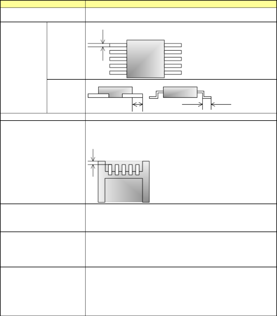
Electrode
Width
Set the width of the electrode size.
Length
Set the length of the electrode size.
Measurement Height Offset
Set the measurement height offset.
Lead Offset
Set the length from the end point of the component outer dimension to
the tip of the lead.
The items for which you can enter a value vary depending on the
component type.
Exposure Time
Set the exposure time of the camera built in the coplanarity sensor.
If the machine cannot run this check normally with the default value, set
a value from 30 to 90 for a glossy component or a value from 110 to
200 for a matte component.
Check Angle
Set the component angle to be applied when the machine runs a
coplanarity check.
If the machine cannot run this check normally with the default value,
you can specify the check angle in increments of 1 degree.
The check angle can be measured with a coplanarity check.
Alternative Check Angle
Specify whether to allow a component to be rotated against the check
angle to be applied when a coplanarity check is run.
By allowing a component to be rotated at two angles, the machine
becomes able to run a coplanarity check at t
he angle almost equivalent
with the recognition angle, and this prevents the cycle time from
becoming longer.
This alternative check angle can be measured with a coplanarity check.
When the lead width is less than 0.3 mm, the machine may not be able to detect a terminal
correctly unless you specify the correct lead width and the correct electrode size. Enter the
correct values for these menu items.
Part 1 Basic Operation Chapter 4 Creating a Production Program
4-85
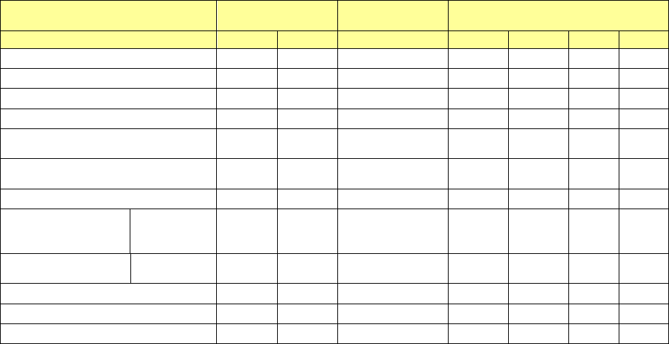
Setting items for each component type
Electrode
Measurement
Height Offset
Lead Offset
Width
Length
Bottom
Right
Top
Left
QFP
○
○
○
○
○
○
○
PQFP (BQFP)
○
○
○
○
○
○
○
SOP
○
○
○
○
×
○
×
TSOP2
○
○
○
○
×
○
×
CON2
(Bidirectional lead connector)
○ ○ ○ ○ × ○ ×
CONZ
(Z-lead connector)
○ ○ ○ ○ × ○ ×
TSOP
○
○
○
×
○
×
○
CONN
(Unidirectional lead
connector)
Leads On
Top
○ ○ ○ × × ○ ×
Leads On
Bottom
○ ○ ○ ○ × × ×
BGA
×
×
○
×
×
×
×
FBGA
×
×
○
×
×
×
×
Others
×
×
×
×
×
×
×
Part 1 Basic Operation Chapter 4 Creating a Production Program
4-86
(9) Vision data
Enter the information to perform centering for the center of the component by VCS camera.
The information to be set depends on the component type
Vision centering is performed by recognizing a bright portion (lead, call, etc.) of the component
through the VCS camera.
At vision centering, it is impossible to detect a fault such as lead vend and ball deformation. In the
vision items, set the lead, ball size, defect detecting level, etc. required for centering and defect
detection.
• Components for vision centering
Component type Vision recognition Lead shape, etc.
Reference: Laser recognition
enable/disable
Square chip
O
O
Square chip p (LED)
X
O
Melf
X
O
Elec. Cap. (Aluminum electrolytic
capacitor)
O
Lead component
O
GaAsFET
O
Lead component
O
SOT
X
O
SOP
O
Lead component
O
HSOP
O
Lead component
O
SOJ
O
Lead component
O
QFP
O
Lead component
O
QFN
O
Lead component
O
PLCC (QFJ)
O
Lead component
O
PQFP (BQFP)
O
Lead component
O
TSOP
O
Lead component
O
TSOP2
O
Lead component
O
BGA
O
Ball component
O
FBGA
O
Ball component
X
Outline-recognized component
O
Components whose
outline is to be recognized
X
General-purpose vision component
O
Components whose
outline is to be recognized
X
RNA (Network resistor)
X
O
Trimmer
X
O
One-direction lead connector
O
Lead component
O
Two-direction lead connector
O
Lead component
O
Z-lead connector
O
Lead component
O
Expanded-lead connector
O
Lead component
X
J-lead socket
O
Lead component
O
Gull-wing socket
O
Lead component
O
Socket with bumper
O
Lead component
O
Other
X
O
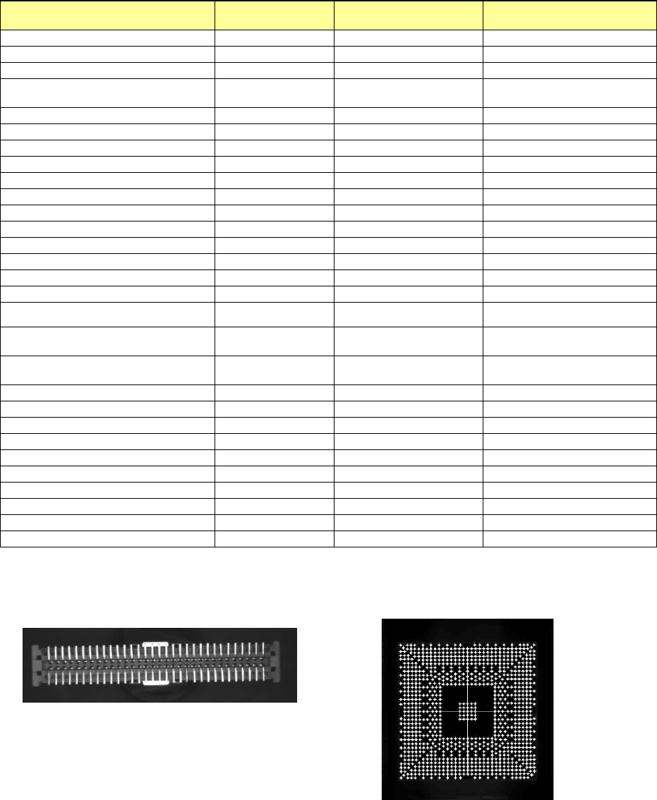
Example 1) For connector component
(lead recognition)
Example 2) For BGA component
(ball recognition)