RS-1_instruction manual.pdf - 第887页
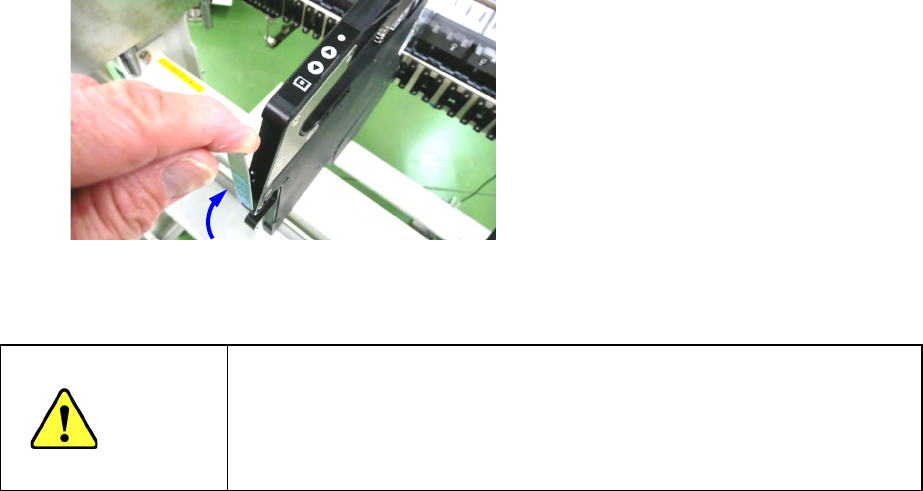
Part 2 D etaile d Descript ion of E ach Functi on Chapter 12 Handling th e Optional Device s 12 -3 (7) Return the lock re lease le ver and check t hat the fee der is clamped. Figure 12.1 - 11 CAUTION After sett ing feede…
Part 2 Detailed Description of Each Function Chapter 12 Handling the Optional Devices
12-2
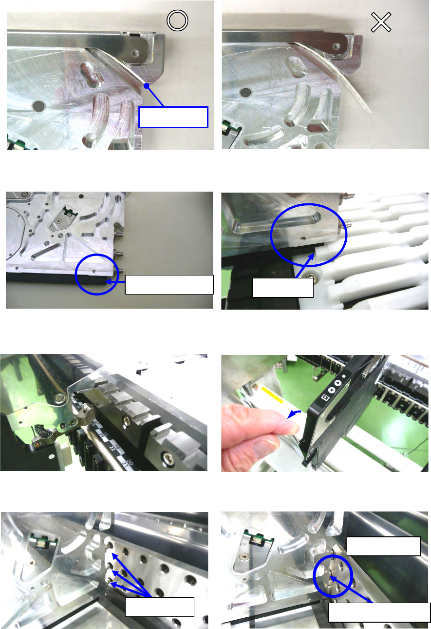
(3) Before attaching the tape feeder on the bank, check to see if the carrier tape does not
protrude 3 mm or more from the tape ejecting slot. If the tape protrudes 3 mm or more, cut it.
Before insertion, confirm that the upper cover is closed.
Figure 12.1-3 Figure 12.1-4
(4) Insert the tip of the slide rail into the groove of the guide rail.
Figure 12.1-5 Figure 12.1-6
(5) After inserting the tape feeder into the middle, pull the rock release lever, open the clamp.
Figure 12.1-7 Figure 12.1-8
(6) Hold down the tape feeder into the bank until the guide pin F hits against the side of the bank.
Figure 12.1-9 Figure 12.1-10
Tip of the slide rail
Guide rail
Guide pin F
Hit against the bank.
Contact tightly.
No Good
3 mm or less
Good
Part 2 Detailed Description of Each Function Chapter 12 Handling the Optional Devices
12-3
(7) Return the lock release lever and check that the feeder is clamped.
Figure 12.1-11
CAUTION
After setting feeders required for PWB production at the positions
specified with a production program respectively, set feeders not to be
used for production at the positions not occupied with the feeders above
so that any finger or hand cannot be put between the set feeders to
secure your safety.
Part 2 Detailed Description of Each Function Chapter 12 Handling the Optional Devices
12-4
12.1.1.2 Setup
To mount and remove a tape, pull out the RF series electric feeder form the RF bank first. Then
conduct the work on the tape reel setup stand for RF feeder (option).
Procedure for setting a tape with the Tape reel setup stand for RF
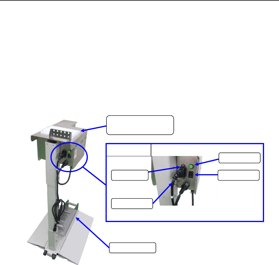
(1) Connect the power plug of the tape reel stand to the AC outlet to supply power to the stand.
(2) Set the power switch to ON. Check to see if the lamp lights.
(3) Attach the RF series Electric tape feeder onto the RF work base.
(4) Place the tape reel on the reel holder, and then set a tape onto the RF series Electric tape
feeder.
(Refer to the Instruction Manual of each RF series Electric tape feeder for how to set a tape
onto it.)
(5) Grasp the grip section of the tape feeder firmly with your hand, and insert the slide rail in the
work base while supporting the lower side of the tape feeder with your opposite hand.
(6) The work-based lane uses a lane of the left edge.
Enlarged view
Power cord
Inlet
Power switch
Power lamp
RF work base
(RF attachment section)
Reel holder