RS-1_instruction manual.pdf - 第532页
Part 1 B asic O peration Chapter 4 Cr eating a Produc tion Progra m 4- 197 (2) T eaching a user - defin ed templat e If any BOC mark is not found on a board or a c ircuit, you can regist er a certa in circuit pat tern as…
Part 1 Basic Operation Chapter 4 Creating a Production Program
4-196
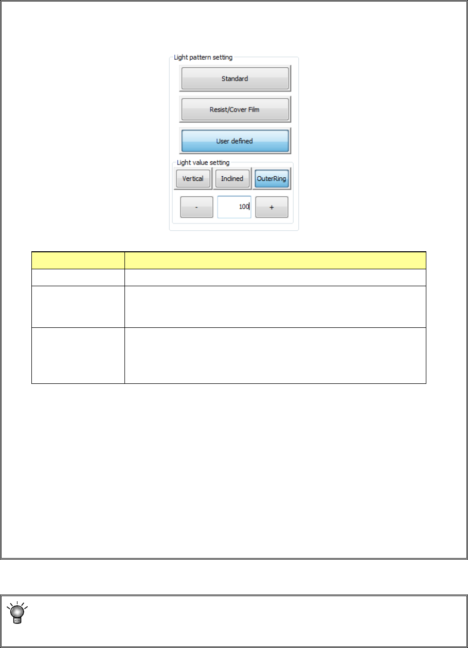
• If the system cannot recognize a mark stably, press the "Light pattern setting" button to set
the light pattern. Be sure to set the light pattern before specifying the top side and left side
of the measurement frame.
When you use the <User defined> button, enter the light value directly.
Select the <Inclined> button, the <Vertical> button or the < OuterRing > button and enter
the desired value into the edit box directly, or change the displayed value with pressing
the <+> button or the <-> button.
* We recommend that you specify a value from 50 to 200 for a user-defined pattern.
If you specify 50 or a smaller value, the amount of light may become unstable.
The [OuterRing] button is displayed only when [Solder Print Misalignment Correction
(option)] is set.
If you want to teach only the inspection frame while holding the same information on a
mark, press the <Next> button. You can skip Step ③.
When the system recognizes a new mark, the <Next> button is disabled.
Light pattern Process
Standard Select this type if the system recognizes a normal BOC mark.
Resist/Cover Film Select this type if a mark is not reflected well with the standard type of
light because a resist or cover film is located over a mark, so the
system cannot recognize the mark stably.
User defined Select this type if a mark is not reflected with either type of the light
above, and the system cannot recognize a mark stably.
This selection allows you to set the light amounts of the vertical,
inclined and OuterRing lights directly.
Part 1 Basic Operation Chapter 4 Creating a Production Program
4-197
(2) Teaching a user-defined template
If any BOC mark is not found on a board or a circuit, you can register a certain circuit pattern as a
BOC mark.
Any pattern (such as a silk screen and wiring) can be selected if it is distinguished from any other
pattern on a board. Select a stable pattern that will not vary depending on boards. We
recommend that you use a pattern (land) as a mark.
To teach a user-defined template, follow the procedure below after teaching starts.
1) Setting the measurement frame
Align the upper side and the left side of the scale frame with the upper edge and the left
edge of the mark, and then select the <OK> button to validate these two sides.
After validating two sides, align the lower side and the right side of the scale frame with the
lower edge and the right edge of the mark in the same manner, and then select the <OK>
button to validate these two sides.
At this point, the system automatically recognizes the mark, and obtains data necessary for
correction.
2) Setting the noise cut level
The system automatically obtains the noise cut level around the mark, and then displays it.
Adjust the noise cut level with pressing the upper/lower sides of the frame so that the mark
can be displayed clearly and the noise around the mark can be reduced as much as
possible.
After adjustment, press the <OK> button.
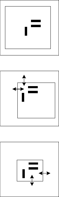
The image shot with the camera and the scale frame are displayed
on the screen.
Pad printing section
First, set the upper side and the left side of the scale frame.
Set the upper side and the left side to be recognized (by moving the
side indicated with the arrow).
When these sides are set, press the <OK> button.
The message “Set Left-Top Point” is displayed on the bottom of the
screen.
In the same manner, set the lower side and the right side of the
scale frame.
After adjustment, press the <OK> button.
The message “Set Right-Bottom Point” is displayed on the bottom
of the screen.
**********
**********
Part 1 Basic Operation Chapter 4 Creating a Production Program
4-198
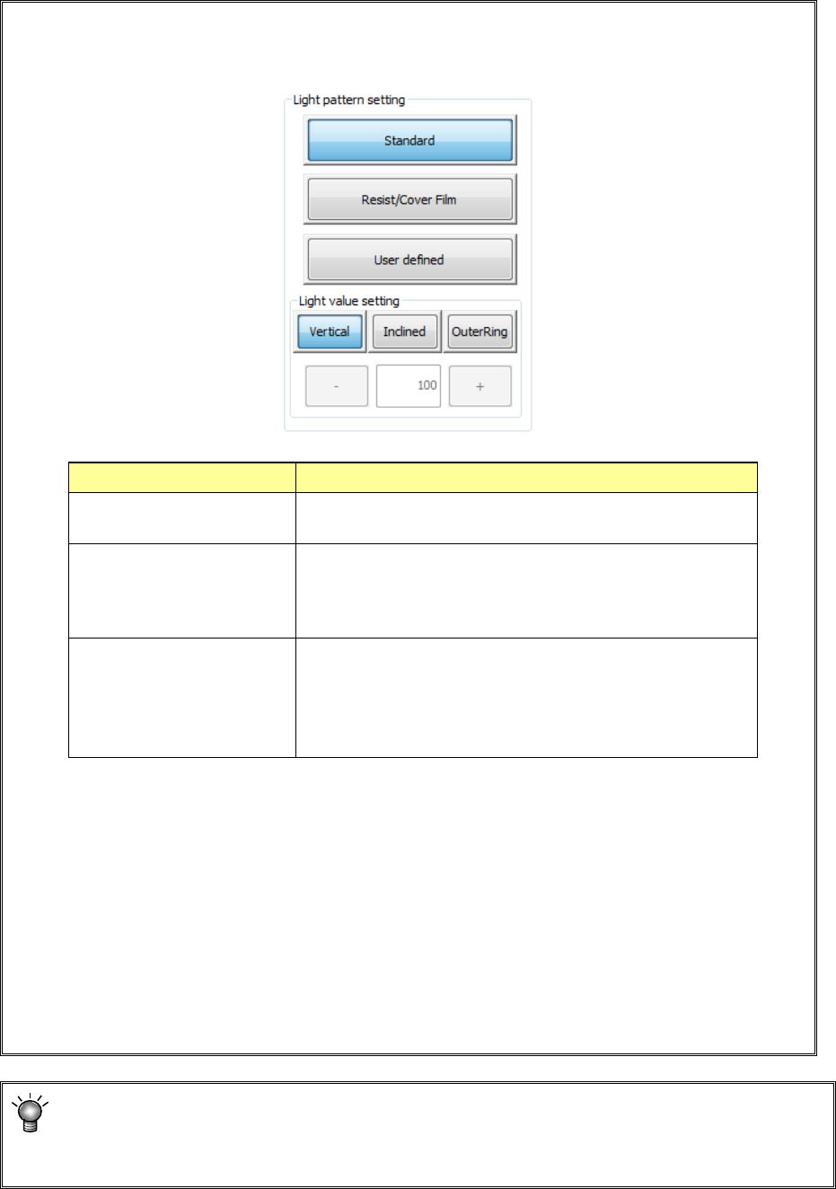
• If the system cannot recognize a mark stably, press the "Light pattern setting" button to set
the light pattern. Be sure to set the light pattern before specifying the top side and left side
of the measurement frame.
When you use the <User defined> button, enter the light value directly.
Select the <Inclined> button, the <Vertical> button or the < OuterRing > button and enter
the desired value into the edit box directly, or change the displayed value with pressing
the <+> button or the <-> button.
* We recommend that you specify a value from 50 to 200 for a user-defined pattern.
If you specify 50 or a smaller value, the amount of light may become unstable.
The [OuterRing] button is displayed only when [Solder Print Misalignment Correction
(option)] is set.
If you want to teach only the inspection frame while holding the same information on a
mark, press the <Next> button. You can skip Step ③.
When the system recognizes a new mark, the <Next> button is disabled.
Light pattern Process
Standard
Select this type if the system recognizes a normal BOC
mark.
Resist/Cover Film Select this type if a mark is not reflected well with the
standard type of light because a resist or cover film is
located over a mark, so the system cannot recognize the
mark stably.
User defined
Select this type if a mark is not reflected with either type of
the light above, and the system cannot recognize a mark
stably.
This selection allows you to set the light amounts of the
vertical, inclined and OuterRing lights directly.