RS-1_instruction manual.pdf - 第901页
Part 2 D etaile d Descript ion of E ach Functi on Chapter 12 Handling th e Optional Device s 12 - 17 12.3.3 Mat rix tray server setup (When a TR8SR i s select ed) 12.3.3.1 Setting up t he TR8SR (RS -1 /1R ) 1) I ndicatio…
Part 2 Detailed Description of Each Function Chapter 12 Handling the Optional Devices
12-16
12.3.2 Setting RS-1/1R (When a TR8SR is selected)
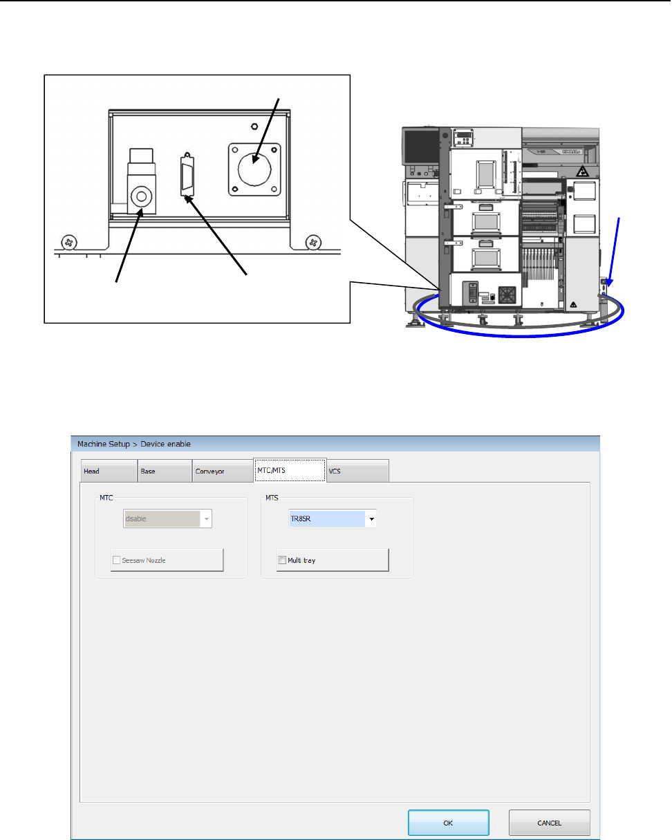
Connect the power cable, communication cable, and air tube to the machine, and then turn ON the
circuit breaker of the TR8SR to supply the power to the mounter.
In this phase, perform the work without inserting the TR8SR into the machine main unit.
In the status where administrator or higher authority is enabled without performing the origin return,
select “TR8SR” in the “Machine Setup > Device enable” window. Save this setting and turn OFF the
power once.
Cable
Air tube
Power connector
Communication
connector
Air tube
Part 2 Detailed Description of Each Function Chapter 12 Handling the Optional Devices
12-17
12.3.3 Matrix tray server setup (When a TR8SR is selected)
12.3.3.1 Setting up the TR8SR (RS-1/1R)
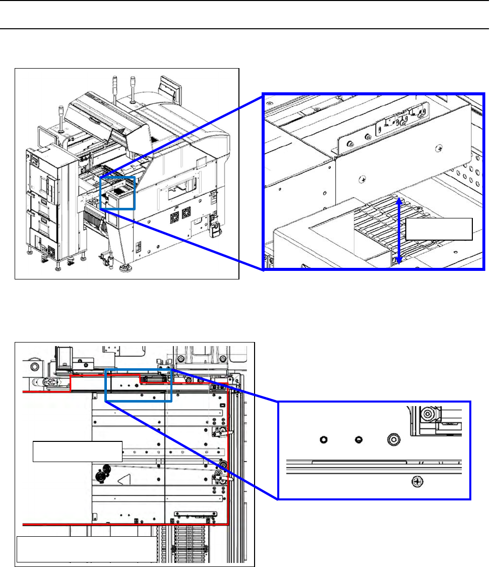
1) Indication of the installation height
2) Rubber stopper abutment.
32mm
RS-1 rear feeder bank
TR8SR body
RS-1/1R rear feeder bank
Part 2 Detailed Description of Each Function Chapter 12 Handling the Optional Devices
12-18
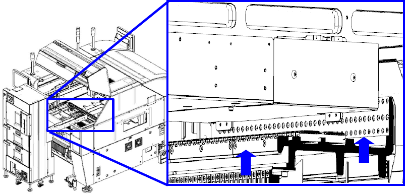
3) Push the main unit stopper against the feeder bank.