RS-1_instruction manual.pdf - 第899页
Part 2 D etaile d Descript ion of E ach Functi on Chapter 12 Handling th e Optional Device s 12 - 15 2) Assembling t he exhaust d uct 3) Remove REG ULA TION_BAR _RS (M4 x 8 4 pc s) TR8SR Assemble attached items M4× 8 4 R…

Part 2 Detailed Description of Each Function Chapter 12 Handling the Optional Devices
12-14
12.3 Installing the Matrix Tray Server (MTS)
This is a device to allow direct pickup by the main unit head and multiple-feed. (Rear bank
installation)
SR-1 can be used TR8SR, TR5SNX and TR5DNX.
Refer to the MTS Instruction Manual for details on handling and setting.
To avoid any accident caused by sudden activation of the machine, turn
off the power.
12.3.1 Setting up RS-1/1R (When a TR8SR is selected)
1) Removal of reel holder B. In the case of the fixed bank specification, it is placed on the floor
and removed as it is.)
CAUTION
Part 2 Detailed Description of Each Function Chapter 12 Handling the Optional Devices
12-15
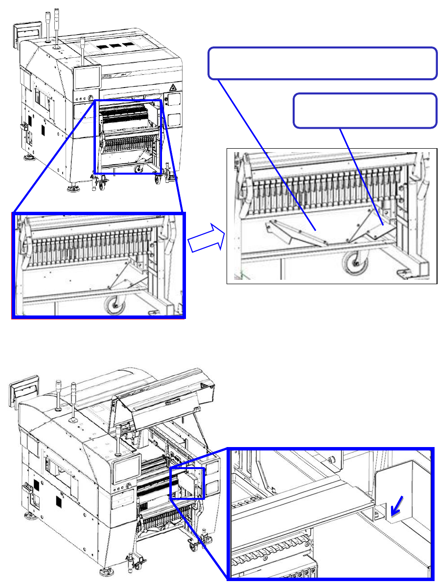
2) Assembling the exhaust duct
3) Remove REGULATION_BAR_RS (M4 x 8 4 pcs)
TR8SR Assemble attached items M4×8
4
Reversed 180 degrees and
installed.
Part 2 Detailed Description of Each Function Chapter 12 Handling the Optional Devices
12-16
12.3.2 Setting RS-1/1R (When a TR8SR is selected)
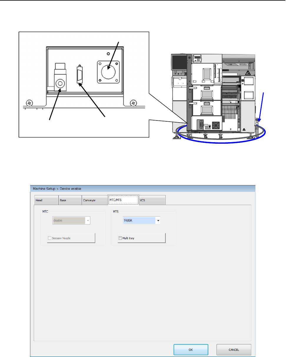
Connect the power cable, communication cable, and air tube to the machine, and then turn ON the
circuit breaker of the TR8SR to supply the power to the mounter.
In this phase, perform the work without inserting the TR8SR into the machine main unit.
In the status where administrator or higher authority is enabled without performing the origin return,
select “TR8SR” in the “Machine Setup > Device enable” window. Save this setting and turn OFF the
power once.
Cable
Air tube
Power connector
Communication
connector
Air tube