RS-1_instruction manual.pdf - 第613页
Part 1 B asic O peration Chapter 4 Cr eating a Produc tion Progra m 4- 278 4.5.7 .7 Bad mark teaching This comma nd uses the O CC unit to check whet her to pr oduce each c ircuit, and t eaches the coordinate s of a bad m…
Part 1 Basic Operation Chapter 4 Creating a Production Program
4-277
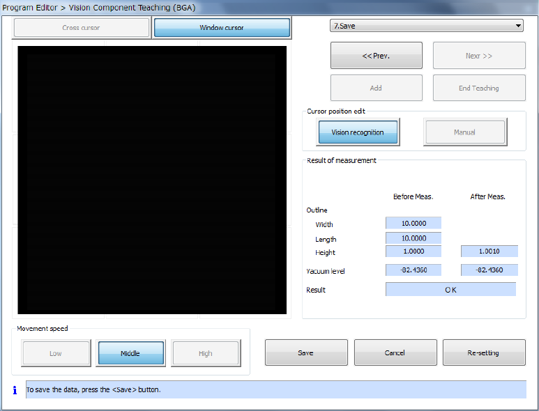
⑧ Saving
After you finish teaching and setting all data, the system recognizes a component.
After recognizing a component, the system displays the screen for saving information on the
result of measurement.
a) Press the <Save> button to save the component vision data. After the system saves the
data, this <Save> button changes to the <Exit> button.
b) Press the <Exit> button to quit the dialog box for performing the vision teaching operation,
and then return to the dialog box for setting the vision teaching operation.
c) When you press the <Cancel> button, the system discards the result of the vision teaching
operation, and then closes the dialog box for performing the vision teaching operation.
d) When you press the <Re-setting> button, the system starts the vision teaching operation
from the beginning again.
Part 1 Basic Operation Chapter 4 Creating a Production Program
4-278
4.5.7.7 Bad mark teaching
This command uses the OCC unit to check whether to produce each circuit, and teaches the
coordinates of a bad mark.
(1) Operation for teaching a bad mark
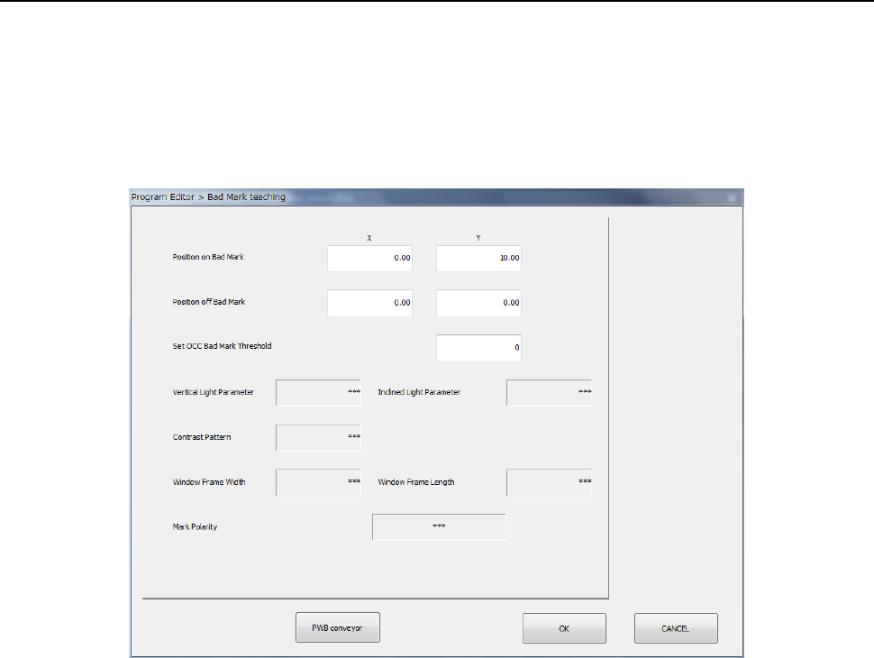
1) Teaching a bad mark
When you select the [Bad mark teaching] command, the following dialog box appears on the
screen.
① Position on Bad Mark
Specify the coordinates of the position at which a bad mark is located on a board. You can
set these coordinates by teaching them.
② Position off Bad Mark
Specify the coordinates of the position at which no bad mark is located on a board. You
can set these coordinates by teaching them. As this position, specify the position
between which the system can distinguish the contrast and that of a bad mark.
③ Set OCC Bad Mark Threshold
Set a threshold value for recognizing a bad mark.
The system automatically determines the threshold value by recognizing a position of a bad
mark and that where no mark is located with teaching operation.
④ Vertical Light Parameter
⑤ Inclined Light Parameter
⑥ Contrast Pattern
⑦ Window Frame (Width, Length)
⑧ Mark Polarity
As an initial value, “***” appears in each of the fields above.
If the system obtains the threshold value successfully when you perform teaching operation
for the “Set OCC Bad Mark Threshold” field to recognize a position of a bad mark and that
where no bad mark is located, the recognized value is set in each of these fields.
Part 1 Basic Operation Chapter 4 Creating a Production Program
4-279
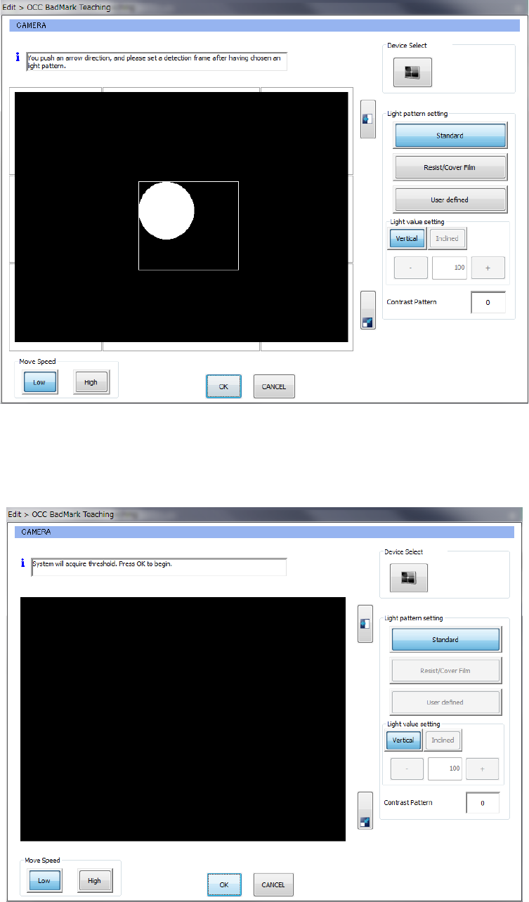
2) Recognizing a bad mark with the OCC (setting the lights)
When you perform teaching operation for the “Set OCC Bad Mark Threshold” field on the
“Bad Mark teaching” screen shown above, the following dialog box appears on the screen.
After selecting the light in the “Light pattern setting” column, press the arrow mark button to
set the detection frame. Then, press the <OK> button.
3) Recognizing a bad mark with the OCC (to set the threshold value)
When you select the light pattern, set the detection frame, and press the <OK> button, the
following dialog box appears on the screen.
When you press the <OK> button on this dialog box, the system obtains the threshold value.