RS-1_instruction manual.pdf - 第190页
Part 1 B asic O peration Chapter 2 Pr oduction 2- 79 9) <S TOP> sw it ch When you pres s the <STO P> switch dur i ng PW B producti on, the system pau ses if any stat ion is producing a P WB or it aborts produ…
Part 1 Basic Operation Chapter 2 Production
2-78
4) Action
Item
Description
Head
Moves the head to its waiting position.
When the front panel is enabled, the head moves to the rear side. When the rear panel is
enabled, the head moves to the front side.
Laser wave
Displays the “Laser wave” screen to allow you to check the laser waveform.
See Section 2.15.7 “Protecting a component” for details.
Image data Save file
Outputs a shot image from the image processing unit to the storage device of the mounter.
Machine data Save
file
Displays the screen for obtaining information on the machine and saving it to allow you to
save the machine information.
See Section 1.10 “Get and Save Machine Data” for details.
Cover Lock Release
Unlocks the protection cover.
5) Edit Data
These buttons allow you to change data being used for the current PWB production.
They are not shown at end of PWB production.
See the description of the “Edit Data” buttons of Section 2.15.1 “If an error occurs” for details.
See the description of Section 2.11.2 “Change Data” for details about how to change the data.
6) Restart mode
Specify how to restart PWB production by pressing the <START> switch when the system
stops it temporarily.
These buttons are not shown at end of PWB production.
See the description of the “Restart mode” buttons of Section 2.15.1 “If an error occurs” for
details.
7) Execution mode
Select whether to produce PWBs continuously or stop in every step.
These buttons are not shown at end of PWB production.
See the description of the “Execution mode” buttons of Section 2.15.1 “If an error occurs” for
details.
8) <START> switch
When you press the <START> switch during PWB production, the system restarts the
production according to “Restart mode” you selected.
CAUTION
Immediately after you press the <START> switch, the head starts moving and
the system starts production.
To avoid injuries, do not put your hands inside the machine or keep your face or
head away from the machine.
Before pressing the <START> switch, check to see if there is no one who is
working the internal parts of the machine.
Before pressing the <START> switch, check to see if there is no one who is
near the machine and may be injured.
Before pressing the <START> switch, check to see if there is no obstacle such
as an adjustment tool that is located or attached inside the machine and may
prevent the machine from operating normally.
Part 1 Basic Operation Chapter 2 Production
2-79
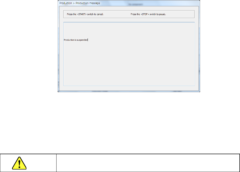
9) <STOP> switch
When you press the <STOP> switch during PWB production, the system pauses if any station
is producing a PWB or it aborts production if there is no station producing a PWB.
When you press the <STOP> switch, the system aborts PWB production.
The system moves down the Support plate so that you can take out a board.
It also removes the nozzle attached on the head.
When you press the <START> switch at this point, the system displays the “Retry list” again.
When you press the <STOP> switch, the system displays the production start screen again.
Even though you abort the current PWB production, the XY-axes and the nozzle heads keep
operating to replace a nozzle with another one.
When these parts finish operating, the clamped board is released.
CAUTION
When you press the <STOP> button, the system starts replacing nozzles.
To avoid a risk of injury, do not place your hand in the machine, nor move your face or
head close to the machine while the machine is operating.
Part 1 Basic Operation Chapter 2 Production
2-80
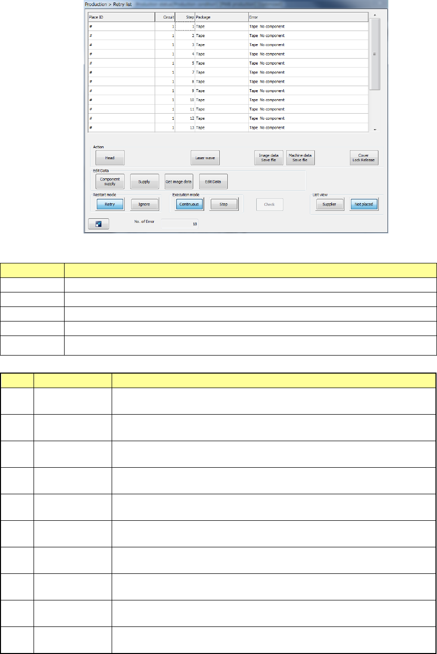
(2) Retry list (not placed)
The displayed menu items except for the listed data itself are the same as those of the “Retry
list (Supplier).”
1) Retry list (Unplaced)
The errors are displayed in occurrence order.
Menu item
Description
Place ID Displays the component ID of a component that the machine failed to place on a board.
Circuit
Displays the number of a circuit that the machine failed to place on a board.
Step Displays the placement step in which the machine failed to place a component.
Package
Displays the package of a component that the machine failed to place on a board.
Error Displays the cause of a component placement failure.
2) Error (Type)
No.
Error
Cause
1 Mark recognition
Since the machine failed to recognize an area mark, it was not able to place the
component on the board.
2 VCS Recog.
Since the machine failed to recognize a component with a VCS, it was not able
to place the component on the board.
3 LA Recog.
Since the machine failed to recognize a component with laser, it was not able to
place the component on the board.
4 Component
The machine failed to place a component on the board due to the component
itself such as its irregular shape.
5 Feeder
The machine failed to place a component on the board because components
run out on a tape, a stick or a holder.
6 MTC
The machine was not able to place a component on the board because
components run out on the MTC supply unit or the unit malfunctioned.
7 MTS
The machine was not able to place a component on the board because
components run out on the MTS supply unit or the unit malfunctioned.
8 DTS
The machine was not able to place a component on the board because
components run out on the DTS supply unit or the unit malfunctioned.
9 Setting
The machine failed to place a component on the board due to wrong setting
such as setting of the Setup application.
10
Copla
(Coplanarity)
The machine was not able to place the component on the board due to a failure
during coplanarity check.