RS-1_instruction manual.pdf - 第372页
Part 1 B asic O peration Chapter 4 Cr eating a Produc tion Progra m 4- 37 (4) A ngl e Enter the com ponent placement angle with re garding the “ Suppl y an gle ” spe cified on the “ Compone nt ” data scr een as the r efe…

Part 1 Basic Operation Chapter 4 Creating a Production Program
4-36
4.3.4.2 Creating Placement data
Enter a value in each of the “Component ID,” “X,” “Y, ” “Angle” and “Component name” fields. The
corresponding initial value is automatically entered in the other fields (the “Head,” “Mark,” “Area
Bad Mark,” “Skip,” “Trial” and “Layer” fields). Change the value(s) in these fields when necessary
only.
Note that each coordinate indicates the distance from the “board reference position” determined
on the “PWB” data screen (“Circuit origin” of the reference circuit for a multi-plane PWB).
(1) Pick
The component pick-up position set when you open the “Placement” data list screen is shown
here.
An asterisk mark (“*”) appears when the component pick-up position is not determined.
When there are multiple feeders for the same component, the pick position is determined by
executing optimization.
When there are not multiple feeders for the same component, the pick position is determined
without executing optimization.
When there are two or more pick data records for the same component type, the pick-up position
of the first one appears, and a plus mark (“+”) appears to the left of this position. You cannot
enter any value in this field.
(2) Placement ID
Enter the placement location as a reference notation. Therefore, this does not have any
influence over placement.
When this item is entered, the default value is applied to each item in which the default value can
be entered, and then displayed.
In addition, this item can be omitted by clicking another item (such as an X coordinate) without
entering any data.
In this case, a "#" mark will be entered here automatically.
(3) X and Y
As the input method, numeric input, teaching input, and data conversion from Flexline CAD are
available.
* Be sure to perform a BOC alignment operation before teaching it. When BOC alignment is not
executed, put a checkmark in the check box “Align placement position with BOC” on the
“Teaching” tab of the “Operation option” screen.
As a coordinate, enter the distance from the “PWB origin” (or circuit origin for a multi-plane PWB)
determined on the “PWB” data screen to the component placement position (center of a
coordinate).
・ Entry of an absolute position:
Enter a numeric value from a keyboard.
You can assign a sign, “+” or “–“ (minus) for a value.
・ Entry of a relative position:
When you enter “++” before a numeric value, the entered value is added to a value
displayed in the field on which the cursor is located.
When you enter “—“ before numeric value, the entered value is subtracted from a value
displayed in the field on which the cursor is located.
When you enter “+=” before a numeric value, the entered value is added to a value in the
field one line above the field on which the cursor is located.
When you enter “-=” before a numeric value, the entered value is subtracted from a value
displayed in the field one line above the field on which the cursor is located.
Note: You cannot enter a space between two symbols, ++, --, += or -=.

Part 1 Basic Operation Chapter 4 Creating a Production Program
4-37
(4) Angle
Enter the component placement angle with regarding the “Supply angle” specified on the
“Component” data screen as the reference angle.
See the description of “JUKI’s definition of the component supply angle” under Section 4.3.5.2 (2)
“Packaging style” for the component supply angle.
(5) Component name
Enter the name of a component (up to 60 characters).
Each time a component name is entered, component data is created.
If the use of database is set when a component name is entered, the database is searched.
Then, if the same component name is detected, the component data is fetched into the program.
Upper-case characters and lower-case characters are handled as the same data but are indicated
with distinction on the display unit.
If the component name is registered in the database in advance, it is replaced with a component
name of the registered characters in the database.
(If the component name is a new one, it is displayed as it is entered. If the component name
already exists, this existing component name is displayed.)
(6) Head
Specify a head to be used for placing a component on a board.
You can select from a pop-up menu a head that is to be used to place a component when a PWB
is produced in Input order.
Auto
A head to be used is selected automatically.
Head1
The head 1 is specified.
Head2
The head 2 is specified.
Head3
The head 3 is specified.
Head4
The head 4 is specified.
Head5
The head 5 is specified.
Head6
The head 6 is specified.
Head7
The head 7 is specified.
Head8
The head 8 is specified.
“AUTO” is selected as the initial setting. When you execute the “Optimization” utility after
creating a production program, the system automatically selects the optimal head.
(7) Mark (Mark ID)
Select whether to correct a component placement position with an area mark when the system
places a component on a board from the pop-up list box.
When you enter the Placement ID, “No” (a mark is not to be used) is set in the “Mark” field by
default.
“No” or a mark ID (up to eight half-sized characters) is displayed in the “Mark” field on the screen.
To change the setting, touch the input field to open the pop-up menu, and then select the desired
command.
No.
Specify that any marks are not to be used.
Edit
Opens the “Area Mark” screen.
Browse
Opens the “Area Mark” screen. (You cannot edit any data on this screen.)
If you open the pop-up menu when two or more lines are selected, the [Edit] command is not
displayed on the pop-up menu.
Otherwise, three choices shown above are displayed.
When you select the [Edit] command, the “Area Mark” screen appears in Edit mode.
When you select the [Browse] command, you cannot edit any data on the “Area Mark” screen.
Part 1 Basic Operation Chapter 4 Creating a Production Program
4-38
When you select the [Edit] command or the [Browse] command on the pop-up menu invoked from
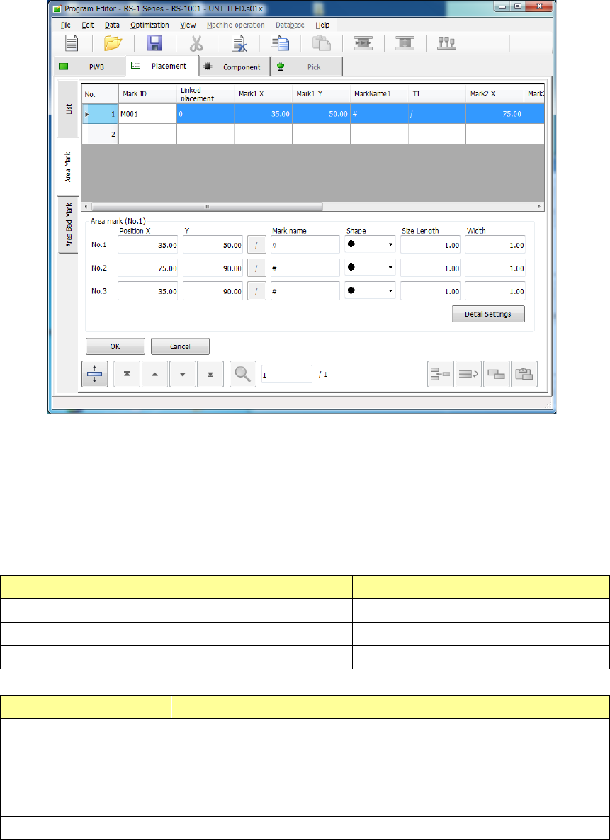
the “List” screen or when you select the “Area Mark” tab, the “Area Mark” editing screen appears.
In the mark group list, a table of registered groups is displayed.
Select a group to be used in this table.
To register a mark, move the focus to a line in which no data is entered yet and enter the
X-coordinate and Y-coordinate of the mark.
After that, perform mark teaching or perform copying from the mark data to obtain the mark data.
The “Area mark” editing screen can be opened by the following method.
The processing varies depending on each display mode.
Operation Screen mode
[Edit] is selected on the mark pop-up menu. Edit/selection mode
[Browse] is selected on the mark pop-up menu Selection mode
The “Area Mark” tab is touched. Edit mode
Screen mode Contents of Processing
Selection mode
The mark data to be used by the placement data is registered. The
cursor on the list is displayed in a line selection status. The <OK> button
is indicated in light color.
Edit mode The coordinates of the mark can be entered and the mark teaching data
can be registered. The <Select> button is not displayed.
Edit/selection mode Selection and editing can be performed simultaneously.