RS-1_instruction manual.pdf - 第32页
Part 1 B asic O peration Chapter 1 Overv iew of the Machine 1- 14 Configuration of the hea d unit The head unit c onsists o f the laser sensor use d to detect plac ement and angle of fsets of the component, and the Z sli…
Part 1 Basic Operation Chapter 1 Overview of the Machine
1-13
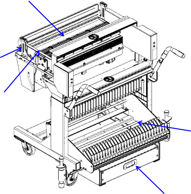
Part names of the overall exchange feeder trolley for the electric tape feeder
Set the tape reel in the reel holder ①.
Raise the E-bank ② and make the positioning with the locate pin ③.
When changing the tape at the setup position, connect the setup connector ④ to the connector on
the ETF side.
Tape reel exchange of RF series electric feeder is done on the set-up stand for electric feeder
(optional).
Carrier tapes, which have been cut during operation of the mounter, accumulate in the trash box ⑤.
①
Reel holder
③
Locate pin
⑤
Trash box
②
E-bank
④
Setup connector
⑤
②
④
③
①
Part 1 Basic Operation Chapter 1 Overview of the Machine
1-14
Configuration of the head unit
The head unit consists of the laser sensor used to detect placement and angle offsets of the
component, and the Z slide shaft which can be moved up and down, or be turned. The machine is
equipped with the head unit as shown below.
① Nozzle outer ④ Z slide shaft ⑦ Head up cylinder
② LNC120 sensor ⑤ θ-axis motor ⑧ Filter box
③ Z-axis motor ⑥ Ball screw
①
②
③
④
⑤
⑥
⑦
⑧
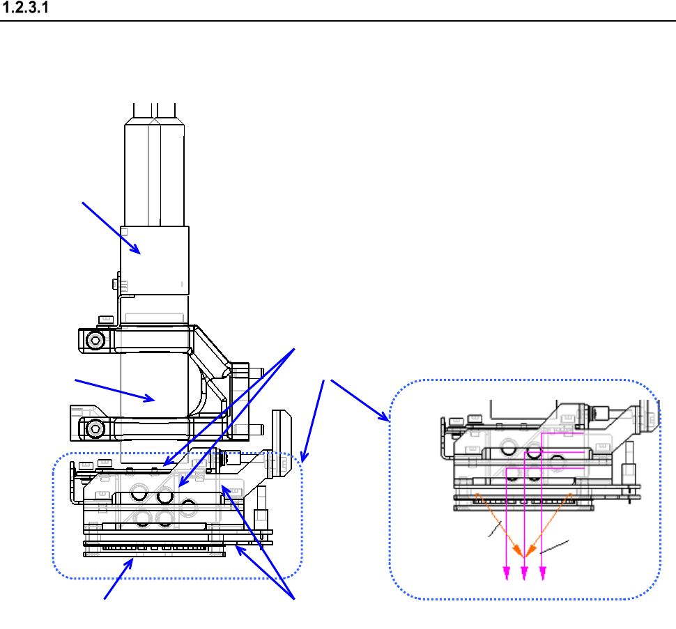
Part 1 Basic Operation Chapter 1 Overview of the Machine
1-15
Configuration of the OCC
The camera detects a BOC mark and corrects the detected mark automatically.
The machine is equipped with a coaxial light and polarizing filter as the standard devices.
* The light for the OCC is controlled to be turned on according to the time for the click of the
shutter of the camera to shoot an image.
Therefore, if you teach a position or some other substance, the OCC light flashes
continuously.
①
CCD camera
② OCC lens
③ OCC light unit
④ Polarizing filter
⑤ Illumination LED board
Vertical light
Inclined light
②
③
④
④ ⑤
①