RS-1_instruction manual.pdf - 第209页
Part 1 B asic O peration Chapter 2 Pr oduction 2- 98 Teach Bad Mark Reader This button a l lows you t o make set tings of rec ogniti on of a bad mark with the O CC. See Section 8.3.6.2 “Bad m ark sensor t hreshold” of Ch…
Part 1 Basic Operation Chapter 2 Production
2-97
In this case, the taught value is to be entered in both fields, X and Y at the same time
regardless of the position of the input focus, in the “X” field or the “Y” field.
③ Area Marks
You can instruct the system to teach each area mark position. To teach the mark
actually, use the <Teaching> button of the function bar. In this case, the taught value
is to be entered in both fields, X and Y, at the same time regardless of the position of
the input focus, in the “X” field or the “Y” field.
Specify the area mark number in the “Mark Number” field.
④ PWB Info.
The system displays the board transport direction, the stopper position, the layout end,
the board reference position and the BOC mark positions.
⑤ <Recognize BOC Marks> button
The system recognizes BOC marks under the conditions you set.
If mark data is completed temporarily, the system automatically teaches marks, and
creates mark data completely.
See Section 4.3.3.3 “Mark: BOC” of Chapter 4 “Creating a Production Program” for
details.
⑥ < Recognize Area Marks> button
The system recognizes area marks under the conditions you set.
If mark data is completed temporarily, the system automatically teaches marks, and
creates mark data completely.
See Section 4.5.6.2 “Area mark” of Chapter 5 “Creating a Production Program” for
details.
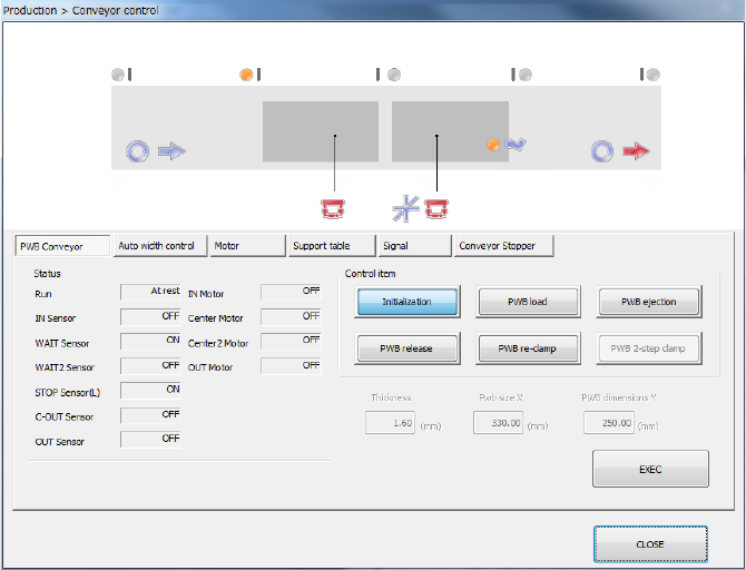
⑦ <Conveyor Control> button
This button controls transporting of a board.
See Section 9.4.1 “Control item: PWB load” of Chapter 9 “Manual Control” for details.
Part 1 Basic Operation Chapter 2 Production
2-98
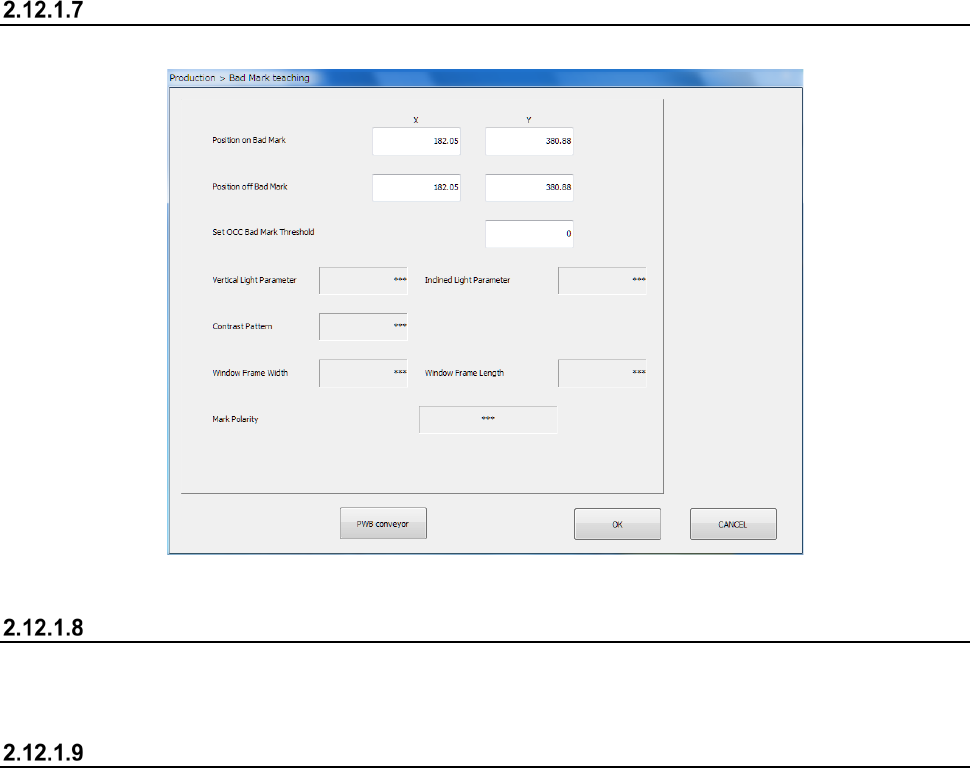
Teach Bad Mark Reader
This button allows you to make settings of recognition of a bad mark with the OCC.
See Section 8.3.6.2 “Bad mark sensor threshold” of Chapter 8 “Machine Setup” for details.
MTS mark recognition
This button causes the machine to recognize a mark of the MTS automatically.
See Section 4.5.6.3 “Feeder bank mark” of Chapter 4 “Creating a Production Program” for details.
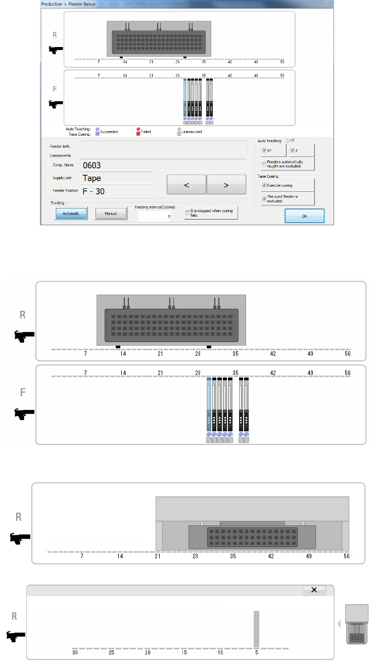
Feeder Setup
This button displays the feeder layout of each bank to allow you to teach and/or track the
component pick-up position.
Only feeders specified with the menu item “Tracking order” on the “Pick position tracking” screen
(see Section 4.5.6.5 “Pick position/Pick height”) are to be traced.
When you press the “Teaching” button displayed in the Operation area, it allows the system to teach
the pick-up position of the selected component.
When you press the “Trace” button displayed in the Operation area, it allows the system to track a
component pick-up operation on the selected bank in the manner selected with the “Tracking”
button, <Automatic> or <Manual>.
Part 1 Basic Operation Chapter 2 Production
2-99
(1) Feeder layout
The system displays the layout of the feeder that is to be used with a production program you
select on the top of the screen.
When a TR8SR is used as a component supply device, the feeder layout is displayed with the
image of a TR8SR as shown below.
When you touch the displayed TR8SR image, the enlarged TR8SR image is displayed.
To return to the original TR8SR image screen, touch “×” or the TR8SR image displayed on
the right side of the screen.
When a component supply device is a TR6S/6D, an image of an MTS is shown on the right
side of the image of the bank.