RS-1_instruction manual.pdf - 第69页
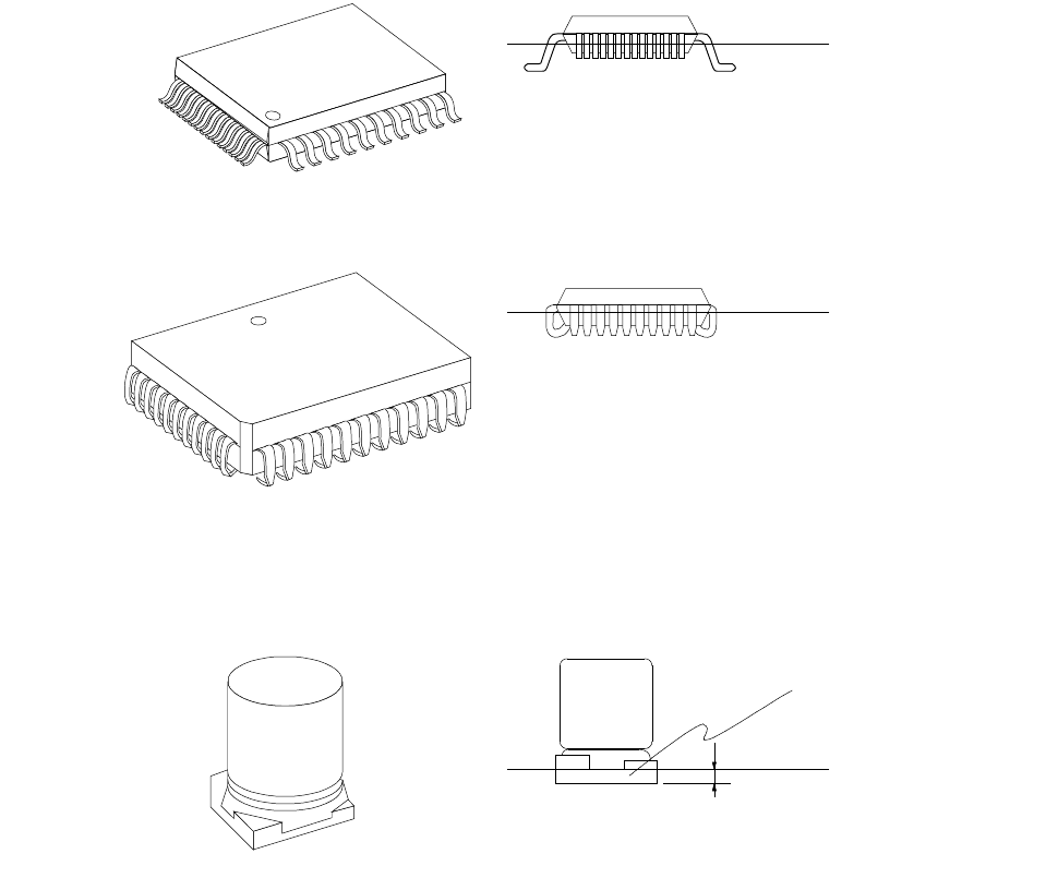
Part 1 B asic O peration Chapter 1 Overv iew of the Machine 1- 51 OFP/BQFP PLCC Elect rolytic capacitor (Between the bottom surface of the mold and the foot of the leads) (0. 3 5 mm from the bottom surface of the mold) M…
Part 1 Basic Operation Chapter 1 Overview of the Machine
1-50
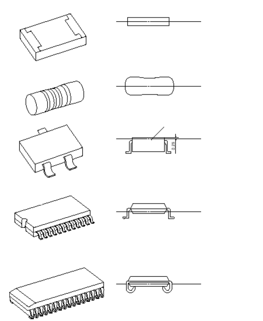
(2) Laser align measurement position for major component types
Mold
Square chip
MELF
SOT
SOP/TSOP
SOJ
(Center between the top and bottom
surfaces of the component)
(Center of the component)
(0.25 mm above the top of the component)
(Center between the bottom surface of the
component and the foot of the leads)
(Center between the bottom surface of the
component and the foot of the leads)
Laser align
measurement position
Laser align
measurement position
Laser align
measurement position
Laser align
measurement position
Laser align
measurement position
Part 1 Basic Operation Chapter 1 Overview of the Machine
1-51
OFP/BQFP
PLCC
Electrolytic
capacitor
(Between the bottom surface of the
mold and the foot of the leads)
(0.35 mm from the bottom surface of the mold)
Mold
Laser align
measurement position
(Center of the vertical section of a foot)
Laser align
measurement position
Laser align
measurement position
0.35
Part 1 Basic Operation Chapter 1 Overview of the Machine
1-52
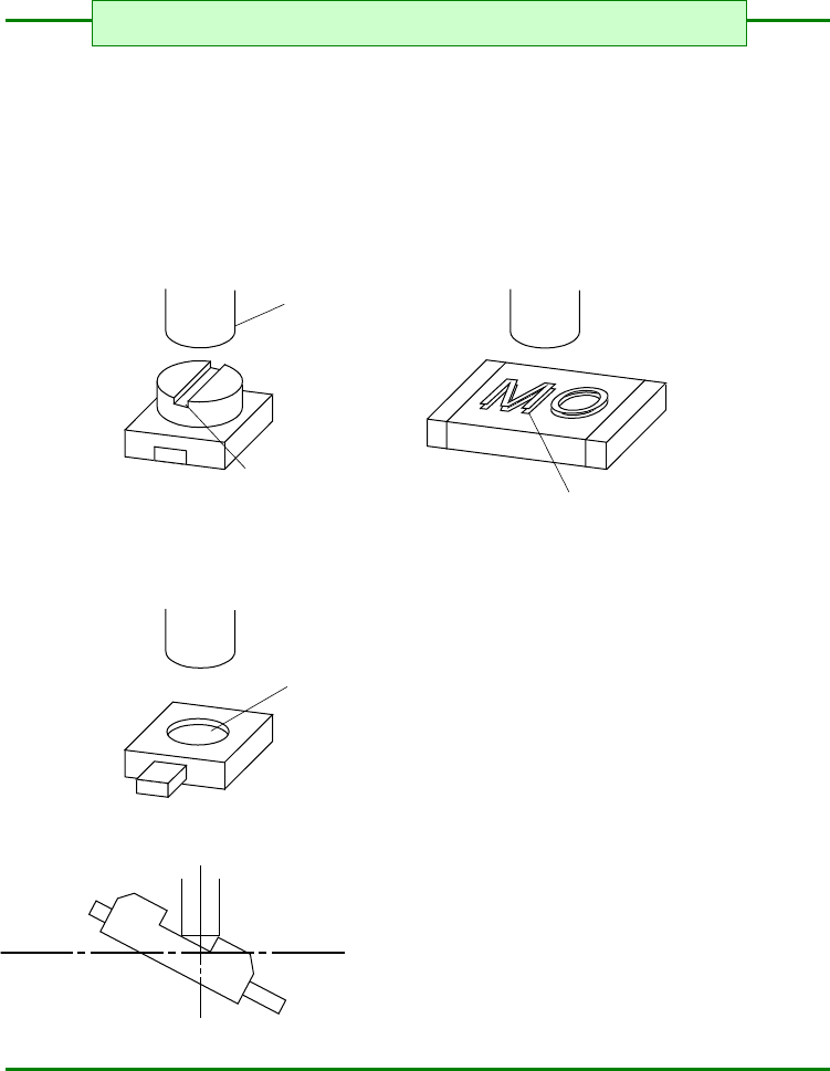
1) A poor pickup or placement accuracy could result if the top surface of the component to be
placed is curved, protruded, or dented. Avoid using such components. (Some such
components may, however, be handled by changing the nozzle number.)
<Typical pickup failures>
<Typical poor placement accuracy>
Pickup nozzle
Slotted groove
Embossed characters
Dented
Laser recognition
§ For the shape of chip components to be mounted §