RS-1_instruction manual.pdf - 第256页
Part 1 B asic O peration Chapter 2 Pr oduction 2- 145 ① S el ect the “ Arrange ” command fr om the men u, and t hen the [Get and Sav e Machine Data] command f rom the “ Arrange ” menu. ② P ress the < …> butt on to …
Part 1 Basic Operation Chapter 2 Production
2-144
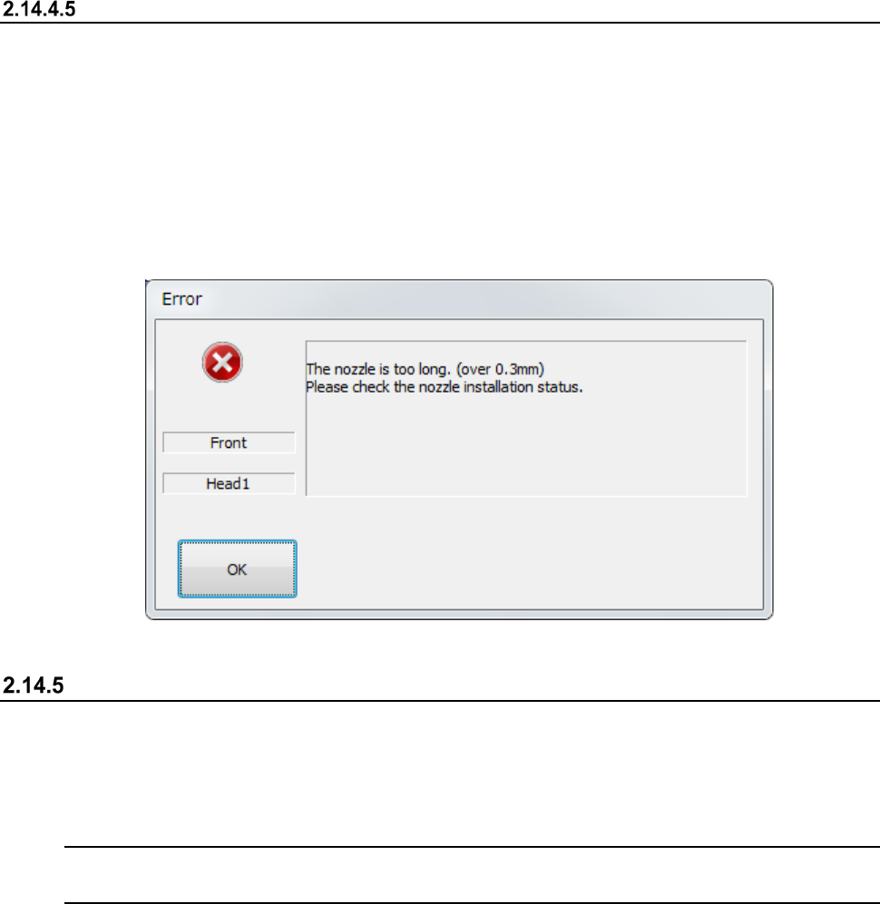
Corrective action to be taken if a nozzle is recognized to be longer than it is
An error indicating that a nozzle is recognized to be longer than it is occurs is supposed to be
caused due to an engagement failure of the Z-axis shaft and the nozzle.
Check the nozzle mounting condition. If it is stained or scratched, polish the nozzle mounting part.
See Section 3.1.11 “Nozzle” for how to check the nozzle mounting condition or polish the nozzle
mounting part.
After polishing the nozzle mounting part, allocate the nozzle.
See section 8.3.2.3 “Nozzle setup” for details of nozzle allocation.
Get and Save Machine Data
When you select the [Get and Save Machine Data] command from the “Arrange” pull-down menu
invoked from the main menu, the message appears on the screen that asks you whether to obtain
and save the machine information.
This function collects machine information files, compresses the collected machine information files,
and saves it into a desired folder when the system is put into the Production Idle state.
Note: Use this function only if our service personnel or your dealer tells you to do so.
Handle the obtained file as instructed too.
How to operate the function
* Before executing this function, obtain and save the machine information on the “Production”
screen.
Part 1 Basic Operation Chapter 2 Production
2-145
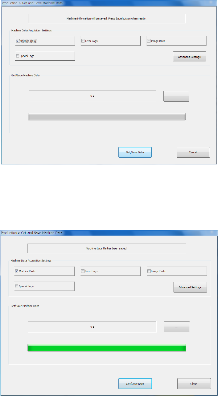
① Select the “Arrange” command from the menu, and then the [Get and Save Machine Data]
command from the “Arrange” menu.
② Press the <…> button to specify where to save the file.
③ When you click the <Get/Save Data> button, the system gets appropriate machine information
files, compresses the obtained files, and saves it.
④ When the machine information files have been obtained and compressed successfully, the
screen display is changed as follows.
To close this screen, press the <Close> button.
See Section 1.9.6 “Get and Save Machine Data” for details.
Part 1 Basic Operation Chapter 2 Production
2-146
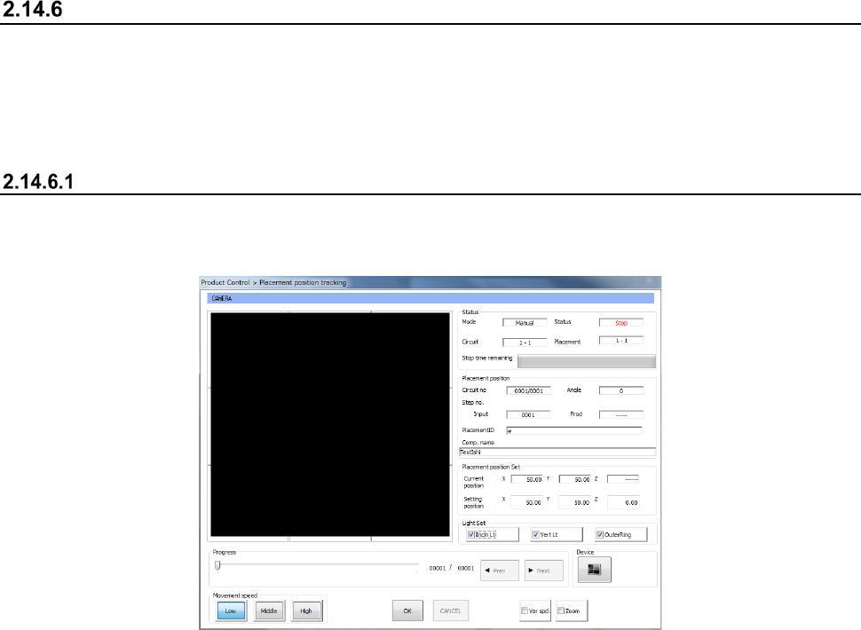
Tracking a component placement position
You can display the list of component placement positions and track whether a component is placed
at each component placement position to check it.
When you select the <Automatic> button or the <Manual> button as the “Place tracking” menu item
on the “Trial” production conditions screen or “Dry run” production conditions screen, the system
tracks a component placement position with a camera after placing a component on a board.
Automatic
When you select “Automatic” as the menu item “Place tracking,” the camera moves to the first
component placement position after a component is placed on a board. The system displays the
“Placement position tracking” screen for each station, and then the monitored image.
• After the camera stops at the position for the time specified in the “Tracking” field, and then
moves to the next component placement position automatically.
When the camera tracks a component whose dimension, width or length, is longer than 4.5
mm, it moves to four corners of the component.
• After PWB production, the camera tracks component placement positions continuously.
• To stop tracking component placement positions with a camera temporarily, press the
<STOP> switch of the operation panel.
• If you press the <STOP> switch when the camera pauses temporarily, the camera stops at
the current component placement position. If you press it when the camera is moving in
this case, the camera stops at the next component placement position.
• When you press the <Teaching> button of the function bar while the camera pauses during
tracking of a component placement position, the system can teach the placement position.
• You can enter a component placement position as a value directly.
When you enter a component placement position and press the <ENTER> button, the head
starts moving.
• When you press the <NEXT> button or the <PREV> button in the “Progress” column, you
can change a component placement position to be taught
- When you press the <START> switch, the system resumes automatic tracking of a
component placement position with a camera.
The head moves immediately to track a component placement position with a camera.
- When you press the <STOP> switch, the system displays the screen for asking you
whether to abort tracking operation, and then aborts tracking of a component placement
position with a camera.
Since the system replaces nozzles even though you press the <STOP> switch, the
XY-axes, nozzles and heads continue moving.